Active cable pay-off device

A pay-off device and active technology, applied in the direction of transportation and packaging, delivery of filamentous materials, thin material processing, etc., can solve the problems of cable accumulation, easily damaged cables, etc., and achieve the effect of protecting cables

Inactive Publication Date: 2021-04-27
侯艳权
View PDF5 Cites 3 Cited by
  • Summary
  • Abstract
  • Description
  • Claims
  • Application Information

AI Technical Summary

Problems solved by technology

[0003] The present invention aims to solve the problem that the existing cable laying-out method is easy to cause cable accumulation and easy damage to the cable

Method used


Image

  • Active cable pay-off device
  • Active cable pay-off device
  • Active cable pay-off device

Examples


specific Embodiment approach 1

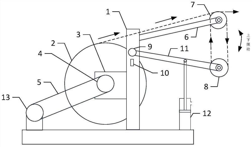
[0031] Specific implementation mode one: refer to Figure 1 to Figure 3 Specifically explain this embodiment, the active cable pay-off device described in this embodiment, in this embodiment, the device includes a wire reel 2, a wire reel support device, a wire reel rotation speed control device and a cable tension change device,

[0032] The reel support device is used to support the reel,

[0033] The reel rotation speed control device comprises a cam mechanism 9, a displacement sensor 10 and a controller,

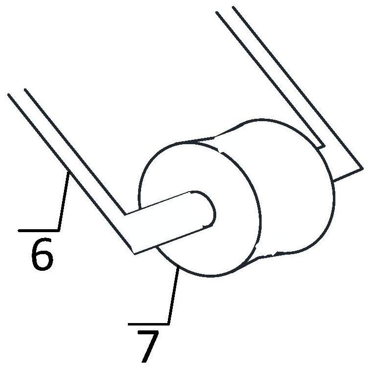
[0034] The cable tension changing device includes No. 1 U-shaped bar 6, No. 2 U-shaped bar 11, cylinder 12, fixed guide wheel 7 and swing guide wheel 8,

[0035] The fixed guide wheel 7 is sleeved on the horizontal bar of the No. 1 U-shaped bar 6, and the two free ends of the No. 1 U-shaped bar 6 are fixedly connected on the two supporting legs of the reel support device.

[0036] The swing guide wheel 8 is sleeved on the horizontal bar of the No. 2 U-shaped bar 11. O...

specific Embodiment approach 2

[0042] Specific embodiment 2: This embodiment is a further description of the active cable pay-off device described in specific embodiment 1. In this embodiment, the reel support device includes a base, a reel support frame 1, a reel, and a reel connection Component 3, wide belt pulley 4, synchronous belt 5, end cover, motor end pulley 13 and motor,

[0043] The reel support frame 1 is fixed on the base, and the two inner walls of the reel support frame 1 are respectively connected with a reel connection assembly 3, and the reel connection assembly 3 has a reel hole, and the reel is inserted into the reel 2. The two ends are respectively inserted into the reel holes, and the reel 2 is supported. One end of the reel is covered with an end cap, and the reel connection assembly 3 is limited on the reel. The other end of the reel is covered with a wide belt pulley 4, and the base is provided with a motor. A motor end pulley 13 is sleeved on the motor output shaft, and a timing bel...

specific Embodiment approach 3

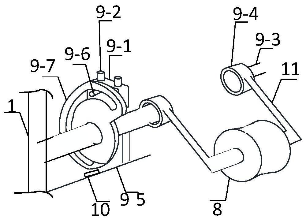
[0046] Specific embodiment 3: This embodiment is a further description of the cable active pay-off device described in specific embodiment 1. In this embodiment, the cam mechanism 9 includes a cam 9-7, a slider 9-1, and a pole 9 -2, connecting shaft 9-3, sleeve 9-4, connecting plate 9-5 and slide bar 9-6,

[0047] The two inner walls of the reel support frame 1 are symmetrically provided with through holes, and the two connecting shafts 9-3 stretch out from the through holes respectively, and the ends of the two connection shafts 9-3 exposed on the outer side walls of the reel support frame 1 are both connected. Covered with nuts, the other ends of the two connecting shafts 9-7 are respectively fixedly sleeved with a sleeve 9-4,

[0048]On the two sleeves 9-4, two free ends of No. 2 U-shaped rods are fixedly connected, and on the connection shaft 9-3 between the inner side wall of the reel support frame 1 and a sleeve 9-4, there is a Cam device 9-7, connecting plate 9-5 is ve...


PUM


Abstract

The invention discloses an active cable pay-off device, and belongs to the field of cable pay-off. The invention aims to solve the problems that the existing cable pay-off mode is easy to cause cable accumulation and easy to damage cables. An air cylinder is inflated with air, a swing guide wheel is pulled down, a cam mechanism and a displacement sensor are arranged on one supporting leg of a winding roll supporting frame, the cam mechanism right faces the displacement sensor, when the swing guide wheel swings at different positions, the distance between the cam mechanism and the displacement sensor is changed, the distance is transmitted to a controller, the controller is used for comparing the distance with an internally set distance value, if the distance is greater than the internally set distance value, the motor speed is not changed, and if the distance is not greater than the internally set distance value, the motor rotating speed is adjusted to a preset speed. The cable pay-off device is used for paying off.

Description

technical field [0001] The invention relates to an active cable pay-off device. It belongs to the field of cable laying. Background technique [0002] During the cable payout process, the payout method is worth noting. Incorrect payout method will not only damage the cable, but also slow down the construction progress. In addition, the existing cable release method only uses manual pulling to release the cable from the reel, which is a waste of manpower. There is also a motor to release the cable, because the motor releases the cable at a constant speed, which will easily lead to cable accumulation and damage. cables, so there is a lack of easy-to-operate pay-off devices suitable for the application. Contents of the invention [0003] The invention aims to solve the problem that the existing cable laying-out method easily causes cables to accumulate and the cables are easy to be damaged. Active cable pay-off device is now available. [0004] Active cable pay-off device...

Claims


Application Information

Patent Timeline
Patent Type & Authority Applications(China)
IPC IPC(8): B65H57/14B65H59/38B65H59/10B65H49/24B65H49/32B65H63/00B65H63/02
CPCB65H49/24B65H49/324B65H57/14B65H59/10B65H59/387B65H59/388B65H63/00B65H63/02B65H2701/34
Inventor 王迎春王义春侯艳权赵晨宇姚越杜欣阳李维李承业
Owner 侯艳权
Why Eureka
Try Eureka