
Ultra-large load cargo elevator structure

A freight elevator and super-large technology, applied in the field of super-large-load freight elevator structure, can solve the problems of large volume, general eccentric load balance effect, complex overall structure, etc. Effect

Active Publication Date: 2021-04-27
HENGDA FUJI ELEVATOR
View PDF6 Cites 1 Cited by
  • Summary
  • Abstract
  • Description
  • Claims
  • Application Information

AI Technical Summary

Problems solved by technology

[0002] Due to the large volume of the super-large cargo elevator in the prior art, there are many mechanical parts, the overall structure is complicated, the installation is inconvenient, and the traction ratio is basically 4:2, so only asynchronous geared traction machines can be used. Expensive, and very bulky, not only inconvenient to transport and install, but also takes up more space in the computer room
In addition, super-large freight elevators often have large trucks coming in and out. When the trucks first enter the elevator entrance, there will be a lot of unbalanced loads, and the freight elevators on the market are basically balanced by the gravity of the elevator. The guide shoes can mainly balance the load on both sides In addition, in the counterweight structure, the car top wheel structure is generally adopted, and there are many horizontal and vertical installation steel beams corresponding to the car top in the machine room, which not only takes up a lot of space, but also The cost of materials is high; in addition, the elevator is lifted by the top wheel of the car, the center of gravity of the elevator is higher, and the moment is larger, which is prone to elevator instability caused by unbalanced load of goods
[0003] Therefore, the existing super large freight elevator structure has the problems of complex structure, inconvenient installation, high manufacturing cost, large floor space, and general balance effect

Method used


Image

  • Ultra-large load cargo elevator structure
  • Ultra-large load cargo elevator structure
  • Ultra-large load cargo elevator structure

Examples


Embodiment

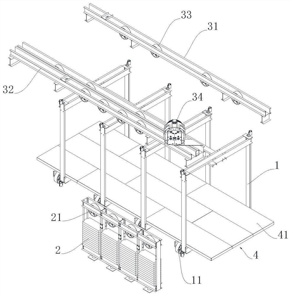
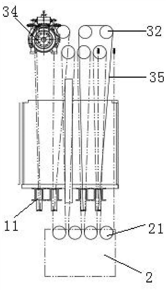
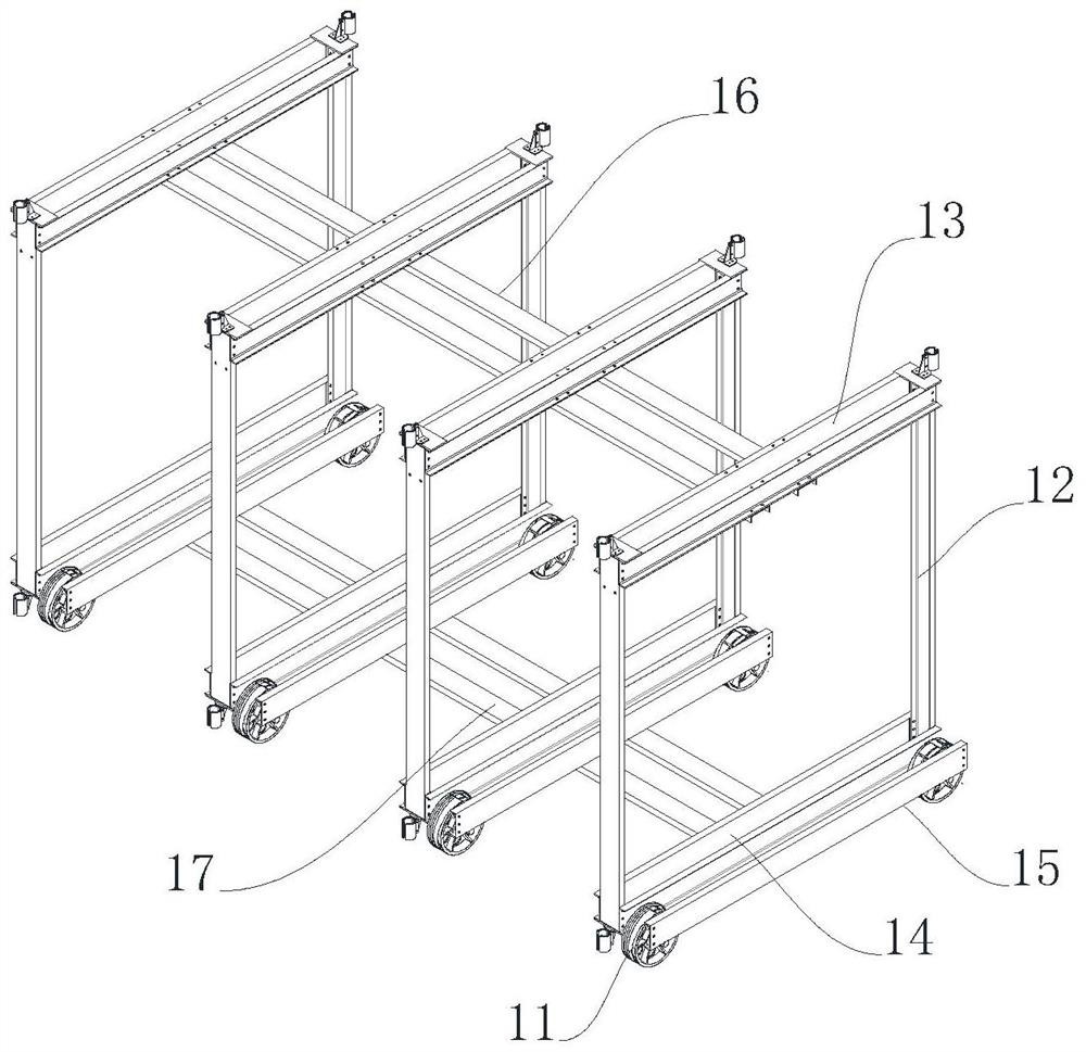
[0030] Such as figure 1 As shown, the super-large load freight elevator structure includes a freight elevator frame composed of four sets of side-by-side car frames 1 and four sets of side-by-side counterweight devices 2. First load-bearing beams 31 are arranged on both sides above the freight lift frame, one of which is the first One side of the load-bearing beam 31 is provided with a second load-bearing beam 32, and four guide wheels 33 are arranged side by side on the first load-bearing beam 31 and the second load-bearing beam 32, between the first load-bearing beam 31 and the second load-bearing beam 32 A traction machine 34 is provided, a counterweight wheel 21 is provided on the counterweight device 2, car bottom wheels 11 are provided on both sides of the bottom of the car frame 1, the traction machine 34, car bottom wheels 11, guide wheels 33 and counterweight The wheels 21 are sequentially connected by a traction rope 35 to form a connection structure with a traction ...


PUM


Abstract

The invention discloses an ultra-large load cargo elevator structure which comprises a cargo elevator frame composed of four sets of parallel car frames (1) and four sets of parallel counterweight devices (2), bearing beams are arranged on the two sides of the upper portion of the cargo elevator frame, guide wheels (33) and a traction machine (34) are arranged on the bearing beams, counterweight wheels (21) are arranged on the counterweight devices (2), and car bottom wheels (11) are arranged on the two sides of the bottoms of the car frames (1). The traction machine (34), the car bottom wheels (11), the guide wheels (33) and the counterweight wheels (21) are sequentially connected through a traction rope (35) to form a connecting structure with the traction ratio of 8: 1. A car bottom (4) is arranged at the bottom of the cargo elevator frame and composed of a plurality of splicing bottom plates (41) which are spliced end to end and distributed in a left-right staggered mode. The ultra-large load cargo elevator structure has the characteristics of simple structure, small occupied area, convenience in mounting, low manufacturing cost and good balance effect.

Description

technical field [0001] The invention relates to a freight elevator structure, in particular to a super-large load freight elevator structure. Background technique [0002] Due to the large size of the super-large cargo elevator in the prior art, there are many mechanical parts, the overall structure is complex, the installation is inconvenient, and the traction ratio is basically 4:2, so only asynchronous geared traction machines can be used. The price is expensive, and the volume is very large, which is not only inconvenient to transport and install, but also takes up more space in the computer room. In addition, super-large freight elevators often have large trucks coming in and out. When the truck first enters the elevator entrance, there will be a large unbalanced load. The freight elevators on the market are basically balanced by the gravity of the elevator. The guide shoes can mainly balance the load on both sides. In addition, in the counterweight structure, the car ...

Claims


Application Information

Patent Timeline
Patent Type & Authority Applications(China)
IPC IPC(8): B66B11/02B66B11/08B66B7/02B66B7/04B66B17/12
CPCB66B11/0226B66B11/008B66B7/022B66B7/047B66B17/12Y02B50/00
Inventor 钱伟华陈博文张爱萍冯聪翁丽曼
Owner HENGDA FUJI ELEVATOR
Learn More