Photovoltaic power generation and mechanical draft cooling tower combined energy-saving and efficiency-improving method and device

A technology of mechanical ventilation and photovoltaic power generation, applied in photovoltaic power generation, photovoltaic modules, water shower coolers, etc., can solve the problems of high cost of distributed photovoltaic power generation, high energy consumption of equipment operation, high outlet water temperature, etc., and increase photovoltaic power generation capacity , Increased operating costs, increased water temperature difference between entering and leaving the tower

Pending Publication Date: 2021-04-27
唐伟明
View PDF18 Cites 1 Cited by
  • Summary
  • Abstract
  • Description
  • Claims
  • Application Information

AI Technical Summary

Problems solved by technology

[0010] In order to overcome the problems existing in related technologies at least to a certain extent, the purpose of this application is to provide an energy-saving and efficiency-enhancing method and device combining photovoltaic power generation and mechanical ventilation cooling towers, which can solve the problem of mechanical ventilation cooling existing in the prior art. The high outlet water temperature of the tower in summer leads to high energy consumption of equipment using cooling water, as well as the technical problems of high cost and low economic benefits of distributed photovoltaic power generation

Method used


Image

  • Photovoltaic power generation and mechanical draft cooling tower combined energy-saving and efficiency-improving method and device
  • Photovoltaic power generation and mechanical draft cooling tower combined energy-saving and efficiency-improving method and device
  • Photovoltaic power generation and mechanical draft cooling tower combined energy-saving and efficiency-improving method and device

Examples


Embodiment 1

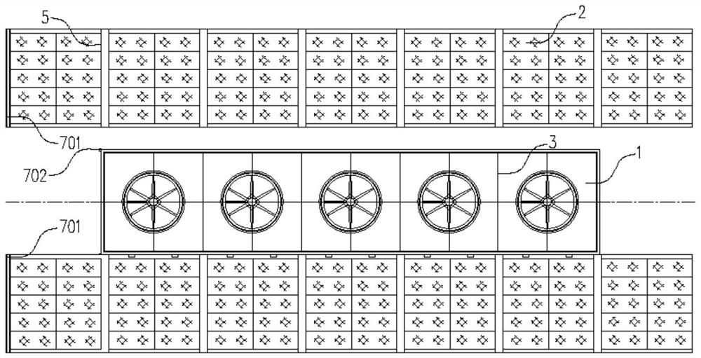
[0058]Such asFigure 1 - Figure 3 As shown, the mechanical ventilation cooling tower 1 is divided into two types and circular shapes in the shape, and there are three types of cross-flow and countercurrent types, and the solar panel 2 for photovoltaic power generation is usually in accordance with the material, packaging of the solar cell. Classification of type, transparency, and combination with buildings.

[0059]The energy saving and efficiency method of the combination of photovoltaic power generation and mechanical ventilation and cooling tower includes the following steps:

[0060]S1, in the vicinity of the mechanical ventilation cooling tower 1 inlet 101, with the column top 102, etc., mounting a group solar panel 2, the solar panel 2 in the air supply direction is 2-6 meters, using the installation of the sun The battery panel 2 is shade the space near the mechanical ventilation cooling tower 1 inlet 101, wherein the solar panel 2 is assembled from the same components into a array...

Embodiment 2

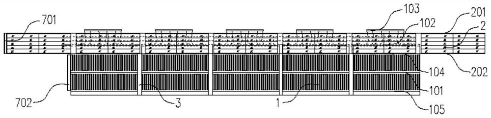
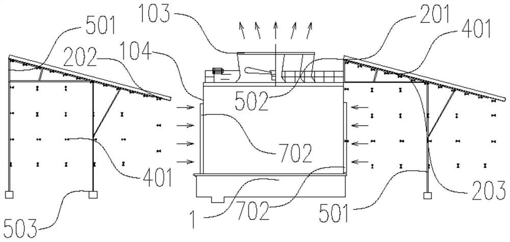
[0087]The present invention provides an energy saving and efficiency device that combines photovoltaic power generation and mechanical ventilation cooling tower, such asFigure 1 - Figure 4As shown, including the mechanical ventilation cooling tower 1, the distributed photovoltaic power generation device 5, the spray cooling device 4, the water supply device 6, and the automatic control device 9, wherein the distributed photovoltaic power generation device 5 includes a plurality of sets of solar panels 2, mounting bracket 501. , Inverter, supply and distribution circuit, etc., solar panel 2 is disposed in the vicinity of the air outlet 101 of the mechanical ventilation cooling tower 1, and the sunshade width of the solar panel 2 in the air supply direction is in the vicinity of the venting tower of the mechanical ventilation cooling tower 1. 2-6 meters, here the solar panel 2 is disposed above the air inlet region of the air inlet 101 of the mechanical ventilation cooling tower 1.

[00...

Embodiment 3

[0125]Such asFigure 1 - Figure 5 As shown, when the tower line 3 of the mechanical ventilation cooling tower 1 is two rows or two rows, the mounting bracket 501 is located between the two rows of column 3, and the upper end 502 utilizes the mechanical ventilation cooling tower 1 South side. The air inlet 101 is fixed to the wind along 104 and extend upward does not exceed the height of the air cylinder 103, and the mounting bracket 501 lower end 503 is fixed in the mechanical ventilation cooling tower 1 mounting ground, and the horizontal distance of the north side of the south side tower 3 is about 1.5. -2.5 m, and the array of solar panels 2 after installation should avoid the tower body and the wind cylindrical 103 of the tower line 3 to block the sun, and the mounting height is not lower than the north side of the southern side of the southern side airhead 101. Windy wind along 104.

[0126]As an alternative embodiment, when the spacing between the two rows 3 is large, the solar pa...


PUM


Abstract

The invention relates to a photovoltaic power generation and mechanical draft cooling tower combined energy-saving and efficiency-improving method and device. The method comprises the following steps: a solar cell panel is mounted above an air inlet region of an air inlet of a mechanical draft cooling tower, and shading and cooling are carried out on the air inlet region through the solar cell panel, the mounting height of the solar cell panel is determined according to the field condition and the mounting inclination angle and is not higher than an air duct of the mechanical draft cooling tower; a spray cooling device is installed in the space from the back face of the solar cell panel to the air inlet lower edge of the air inlet, and the spray amount of the spray cooling device is determined according to the environment humidity and/or the air amount of the mechanical draft cooling tower; and an automatic control device controls a water supply device to pressurize and filter circulating water in the mechanical draft cooling tower and then supply the circulating water to the spray cooling device. By means of the arrangement, the technical problems that due to the fact that an existing mechanical draft cooling tower is high in outlet water temperature in summer, equipment using cooling water is high in operation energy consumption, distributed photovoltaic power generation cost is high, and economic benefits are low can be solved.

Description

Technical field[0001]The present application relates to the field of mechanical ventilation cooling tower and photovoltaic power generation technology, and more particularly to an energy saving and efficiency method and apparatus for photovoltaic power generation and mechanical ventilation cooling tower.Background technique[0002]The existing mechanical ventilation cooling tower is water as a circulating coolant, and the water flows into contact with air and the absorbed heat is discharged to the atmosphere to reduce the water temperature. The mechanical ventilation cooling tower is generally inadequate in summer cooling, and the water temperature is high. The main reason is that the environment is elevated, the humidity is increased; the mechanical ventilation cooling tower is long-term operation, the dispersion coefficient of the filler decreases, resulting in water and air contact The area is reduced; damage is damaged, blocked phenomenon, increase the resistance in the tower, and...

Claims


Application Information

Patent Timeline
Patent Type & Authority Applications(China)
IPC IPC(8): F28C1/00F28F25/02F28F25/10F28F27/00H02S40/42H02S40/10
CPCF28C1/00F28F25/02F28F25/10F28F27/003H02S40/42H02S40/10Y02E10/50
Inventor 唐伟明
Owner 唐伟明
Why Eureka
Try Eureka