Infrared stereo imaging method, system and device

A technology of stereoscopic imaging and infrared imaging, applied in the field of infrared imaging, can solve the problems of life safety risks, non-stereoscopic image plane, unable to play the role of night vision products for accurate observation at night, etc.

Pending Publication Date: 2021-04-27
IRAY TECH CO LTD
View PDF4 Cites 0 Cited by
  • Summary
  • Abstract
  • Description
  • Claims
  • Application Information

AI Technical Summary

Problems solved by technology

[0003] However, the current infrared technology imaging simply displays images, and the displayed images are flat and not three-dimensional, and cannot reflect the level information of depth of field and orientation, and are prone to visual errors. Misjudgment based on the displayed image may pose a risk to life safety

Method used


Image

  • Infrared stereo imaging method, system and device
  • Infrared stereo imaging method, system and device
  • Infrared stereo imaging method, system and device

Examples


Embodiment 1

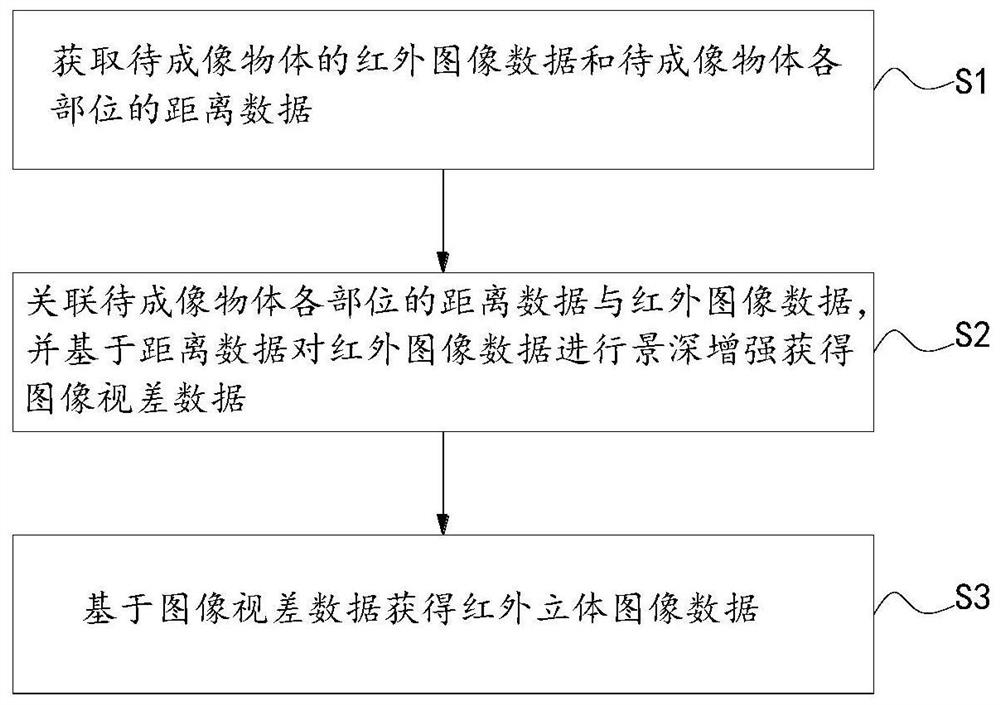
[0042] Embodiment 1: This embodiment provides a kind of infrared stereoscopic imaging method, refer to figure 1 As shown, the method includes:

[0043] S1. Acquire infrared image data of an object to be imaged and distance data of various parts of the object to be imaged.

[0044] Specifically, the infrared image includes image information of each frame of image in the video stream. More specifically, the infrared image includes each frame of infrared image in the video stream collected by the infrared lens, which is an infrared image in RGB format. The distance data is the distance from each part of the object to be imaged to the system for collecting infrared images.

[0045] This step specifically includes:

[0046] S1-1. Receive the original infrared image data of the object to be imaged transmitted by the infrared lens and the byte stream of the distance data of the object to be imaged transmitted by the distance sensor.

[0047] S1-2a. Perform filtering and denoising...

Embodiment 2

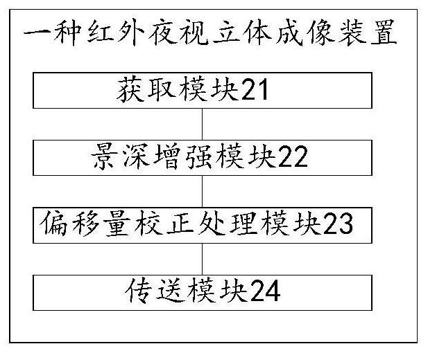
[0082] Embodiment 2: This embodiment provides a kind of infrared stereoscopic imaging system, refer to figure 2 As shown, the system includes:

[0083] The acquisition module 21 is configured to acquire infrared image data of the object to be imaged and distance data of various parts of the object to be imaged, and to obtain infrared stereoscopic display infrared image data based on the image parallax data.

[0084] The acquisition module 21 includes:

[0085] The receiving unit 211 is configured to receive the original infrared image data of the object to be imaged transmitted by the infrared lens and the byte stream of the distance data of the object to be imaged transmitted by the distance sensor; the original infrared image data includes the image of each frame of image in the video stream information.

[0086] The sorting module 212 is configured to sort the distance data byte stream according to a first preset rule.

[0087] A conversion module 213, configured to con...

Embodiment 3

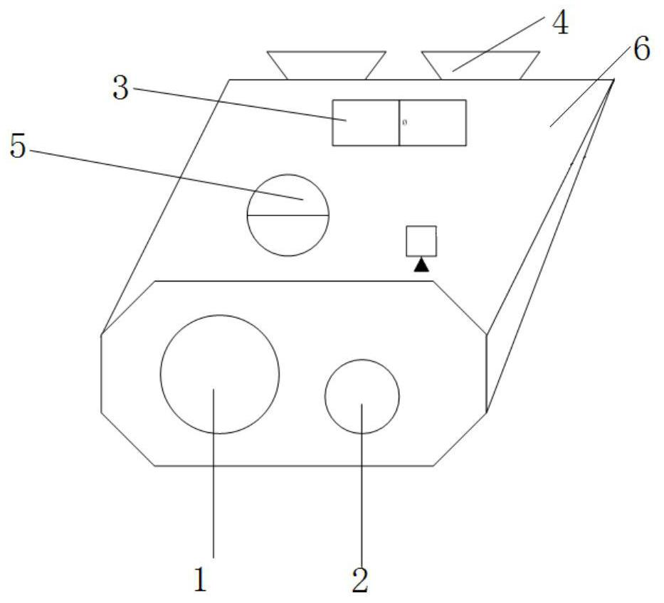
[0099] Embodiment 3: This embodiment provides a kind of infrared stereo imaging equipment, refer to image 3 As shown, the device includes the infrared stereoscopic imaging system 5 provided by the embodiment, and also includes:

[0100] Infrared lens 1, used to obtain the original infrared image data of the object to be imaged;

[0101] The distance sensor 2 is used to obtain the distance data byte stream of the object to be imaged; the distance data byte stream is the distance from each part of the object to be imaged to the infrared lens 1;

[0102] Display screen 3, for displaying infrared stereo images;

[0103] The eyepiece 4 is used to observe the infrared stereo image displayed on the display screen.

[0104] A casing 6 is also included, wherein the infrared stereoscopic imaging system 5 is arranged in the casing 6 .

[0105] Exemplarily, the infrared stereoscopic imaging device provided in this embodiment is an infrared night vision device, and the infrared night v...


PUM


Abstract

The invention discloses an infrared stereo imaging method, system and device. The method comprises the steps: acquiring the infrared image data of a to-be-imaged object and distance data of all parts of the to-be-imaged object; associating the distance data of each part of the to-be-imaged object with infrared image data, and performing depth-of-field enhancement on the infrared image data based on the distance data to obtain image parallax data; obtaining infrared stereoscopic image data of infrared stereoscopic display infrared image data based on the image parallax data; processing the infrared image based on the distance data to enhance the depth of field, and compensating for the problem that the depth of field of the infrared image is insufficient, and displaying a stereoscopic image reflecting the depth of field and orientation to avoid visual errors, so the night accurate observation effect of a night vision product is exerted, and night danger is avoided.

Description

technical field [0001] The invention relates to the field of infrared imaging, in particular to an infrared stereoscopic imaging method, system and equipment. Background technique [0002] In recent years, infrared night vision products have developed rapidly and have been applied to disaster rescue, animal tracking, environmental monitoring and other fields. In scenes with poor night vision, infrared technology can be used to image and observe environments that are difficult to observe at night, and provide tracking and monitoring for search and rescue. Provides great convenience. At present, the existing infrared imaging scheme collects thermal radiation through infrared, forms a complete image with points into a plane, and digitally encodes it and images it on a flat-screen display device to display a complete field of view image. [0003] However, the current infrared technology imaging simply displays images, and the displayed images are flat and not three-dimensional,...

Claims


Application Information

Patent Timeline
IPC IPC(8): H04N13/204H04N13/30
CPCH04N13/204H04N13/30
Inventor 李洋王少龙牟道禄
Owner IRAY TECH CO LTD
Why Eureka
Try Eureka