Intraocular lens positioner

An intraocular lens and locator technology, applied in the field of medical devices, can solve the problems that are not conducive to guaranteeing the quality of the operation and the high requirements for the doctor's experience level

Pending Publication Date: 2021-04-30
叶飞飞
View PDF0 Cites 0 Cited by
  • Summary
  • Abstract
  • Description
  • Claims
  • Application Information

AI Technical Summary

Problems solved by technology

[0004] At present, the positioning of the puncture point and the adjustment of the position of the intraocular lens in suture fixation of the intraocular lens mainly rely on the visual inspection of

Method used


Image

  • Intraocular lens positioner
  • Intraocular lens positioner
  • Intraocular lens positioner

Examples


Embodiment 1

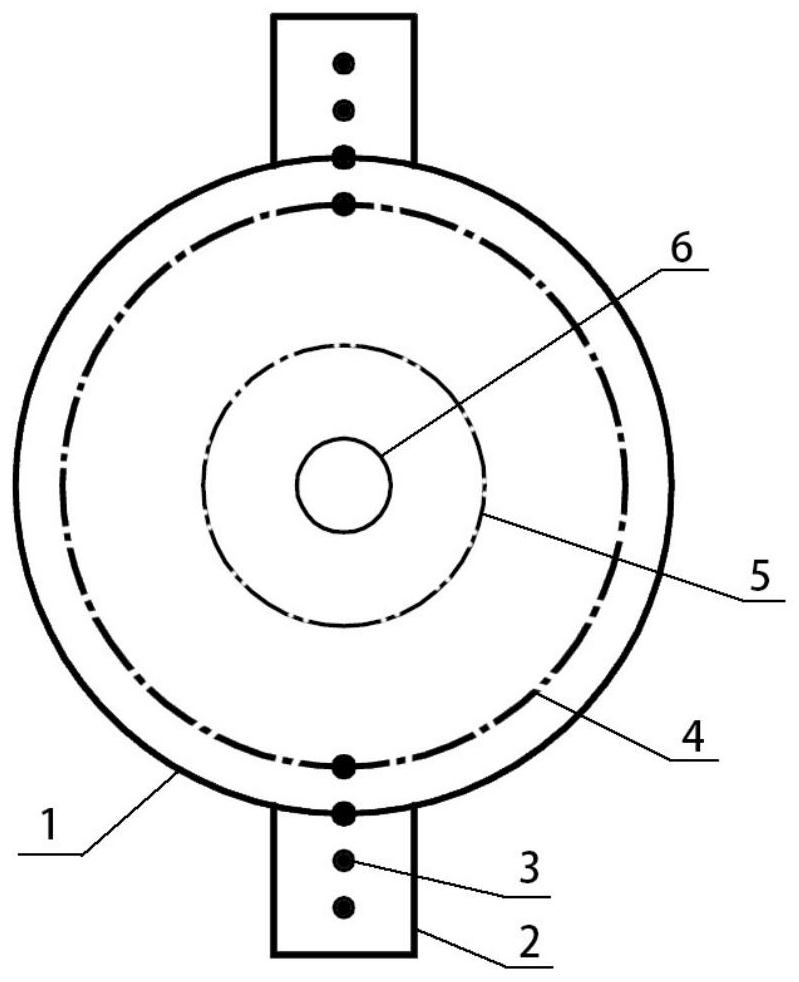
[0030] see figure 1 with Figure 4 , an intraocular lens positioner for intraocular lens suture fixation surgery, comprising a cornea part 1, the cornea part is a transparent arc body, a vent hole 6 is opened in the center of the cornea part, and a vent hole 6 is opened in the cornea part The puncture hole positioning haptic 2 is provided on the edge of 1, the intraocular lens optical part positioning line 5 is provided near the central position of the cornea part 1, and the limbal positioning line 4 is provided near the edge position of the cornea part 1.

[0031] The corneal portion 1 is made of silicon hydrogel with a water content of 36%, its diameter is 14mm, its thickness is 0.09mm, and its base arc radius is 8.6mm. The diameter of the ventilation hole 6 is 2mm. The intraocular lens The diameter of the optical part positioning line 5 is 6 mm, and the diameter of the limbal positioning line 4 is 12 mm.

[0032] Due to the different eyeball sizes of patients, the corneal...

Embodiment 2

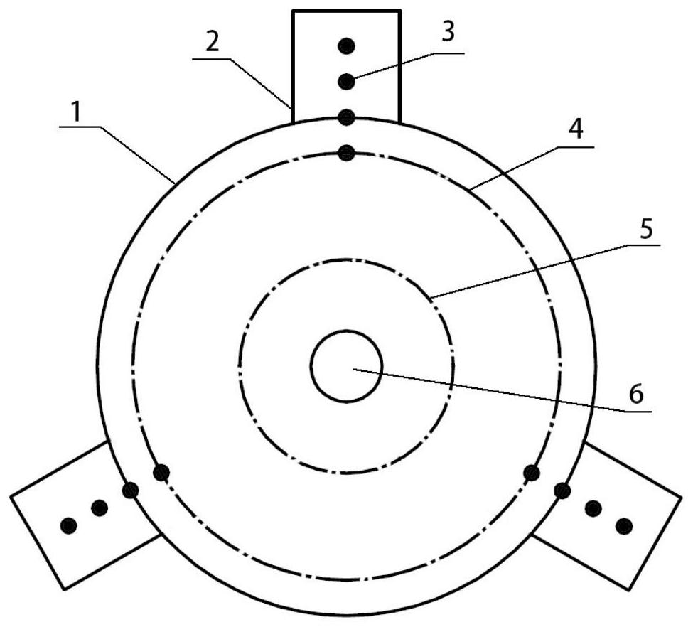
[0037] see figure 2 , an intraocular lens positioner for intraocular lens suture fixation surgery, comprising a cornea part 1, the cornea part is a transparent arc body, a vent hole 6 is opened in the center of the cornea part, and a vent hole 6 is opened in the cornea part The puncture hole positioning haptic 2 is provided on the edge of 1, the intraocular lens optical part positioning line 5 is provided near the central position of the cornea part 1, and the limbal positioning line 4 is provided near the edge position of the cornea part 1.

[0038] The corneal portion 1 is made of silicon hydrogel with a water content of 36%, its diameter is 14mm, its thickness is 0.09mm, and its base arc radius is 8.6mm. The diameter of the ventilation hole 6 is 2mm. The intraocular lens The diameter of the optical part positioning line 5 is 6 mm, and the diameter of the limbal positioning line 4 is 12 mm.

[0039] Due to the different eyeball sizes of patients, the corneal sizes are also...


PUM

PropertyMeasurementUnit
Diameteraaaaaaaaaa
Diameteraaaaaaaaaa
Thicknessaaaaaaaaaa

Abstract

The invention relates to the technical field of medical instruments, and discloses an intraocular lens positioner for intraocular lens suture fixation, which comprises a transparent cornea part, a venthole formed in the center of the cornea part, puncture hole positioning loops arranged at the edge of the cornea part, an intraocular lens optical part positioning line arranged close to the center of the cornea part, and a limbus positioning line arranged close to the edge of the cornea part, the number of the puncture hole positioning loops is two or three, the puncture hole positioning loops are suitable for being implanted into two-loop or three-loop type intraocular lenses respectively, and the puncture hole positioning loops are provided with a plurality of puncture holes which are evenly distributed so as to adapt to the intraocular lenses of different models. During use, the limbus corneae positioning line coincides with the limbus corneae edge of a patient to achieve self-positioning, then a needle can be inserted from the puncture hole in the puncture hole positioning loop, and when the intraocular lens is adjusted to coincide with the intraocular lens optical portion positioning line, the intraocular lens is centered, positioning is convenient and fast, and the situation that visual positioning only depends on doctor experience is avoided. Operation quality is improved.

Description

technical field [0001] The invention relates to the technical field of medical instruments, discloses an ophthalmic surgical instrument, in particular relates to an intraocular lens positioner. Background technique [0002] Intraocular lens (IOL), also known as intraocular lens, is an artificial lens implanted in the eye to replace the natural lens. Membrane rupture and / or rupture of the zonule of the lens, as well as rupture of the posterior lens capsule during cataract surgery, require intraocular lens suture fixation surgery to implant the intraocular lens. [0003] The intraocular lens is usually composed of a circular optical part and surrounding supporting haptics. The diameter of the optical part is generally about 5.5-6mm. Type of thread-mounted supporting loops, on the supporting loops, in the process of intraocular lens suture fixation, it is necessary to implant the intraocular lens first, adjust the position to make the intraocular lens center, and then perform ...

Claims


Application Information

Patent Timeline
IPC IPC(8): A61F2/16
CPCA61F2/1662
Inventor 叶飞飞曾存芳
Owner 叶飞飞
Why Eureka
Try Eureka