Low-grade manganese carbonate polymetallic ore multistage beneficiation device

A manganese carbonate multi-metal, low-grade technology, applied in the direction of magnetic separation, solid separation, chemical instruments and methods, etc., can solve the problems of small contact area between the magnetic roller and the discharge port, uneven distribution of materials, and low screening rate. Achieve the effects of reducing the probability of missed selection, improving the screening accuracy and enhancing the screening effect

Active Publication Date: 2021-04-30
TONGREN UNIV
View PDF5 Cites 1 Cited by
  • Summary
  • Abstract
  • Description
  • Claims
  • Application Information

AI Technical Summary

Problems solved by technology

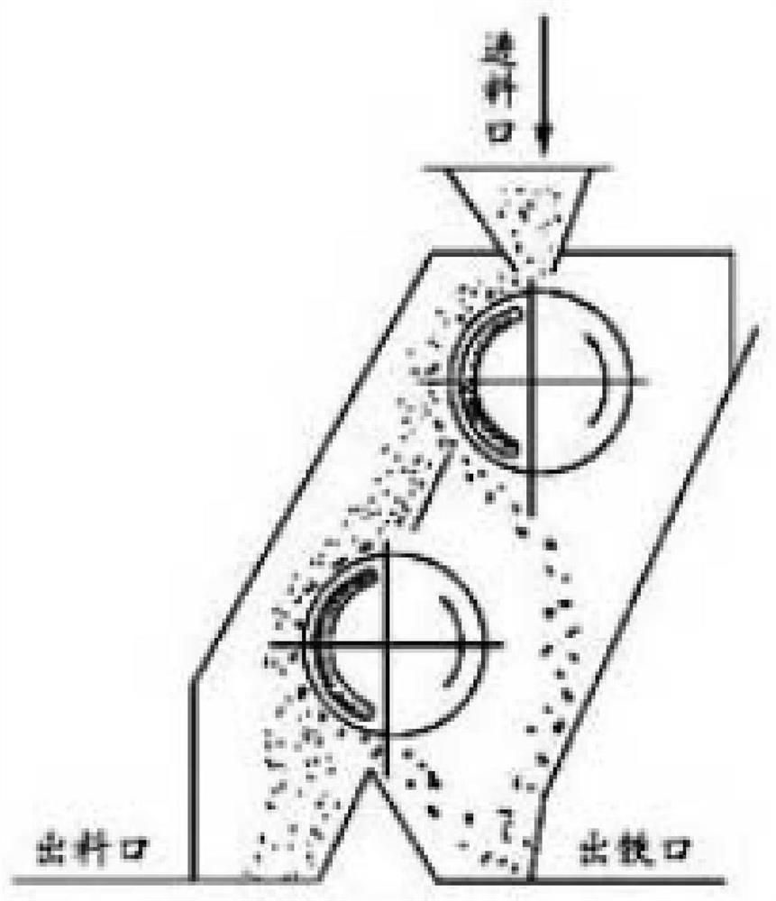
[0004] The disadvantages of the above scheme are: the contact area between the magnetic roller and the discharge port is small, the particle size of the mineral material after ball milling is small, the thickness is thicker when discharging, and the material that can and cannot be adsorbed by the magnetic roller is unevenly distributed. Some places are more, some places are less, and some materials that should be able to absorb with the magnetic roller, because the contact area of ​​the material and the magnetic roller is too small at the moment of falling, and because the outer surface of the magnetic roller is circular, it is bound to cause some The material that can be absorbed by the magnetic roller bounces. After bouncing, it cannot contact the magnetic roller, but falls directly. It is very easy to cause missed selection, which leads to the problem of low screening rate.

Method used


Image

  • Low-grade manganese carbonate polymetallic ore multistage beneficiation device
  • Low-grade manganese carbonate polymetallic ore multistage beneficiation device
  • Low-grade manganese carbonate polymetallic ore multistage beneficiation device

Examples


Embodiment Construction

[0029] The technical solutions of the present invention will be further described below in conjunction with the accompanying drawings and through specific implementation methods.

[0030] Wherein, the accompanying drawings are for illustrative purposes only, and represent only schematic diagrams, rather than physical drawings, and should not be construed as limitations on this patent; in order to better illustrate the embodiments of the present invention, some parts of the accompanying drawings may be omitted, Enlargement or reduction does not represent the size of the actual product; for those skilled in the art, it is understandable that some well-known structures and their descriptions may be omitted in the drawings.

[0031] In the drawings of the embodiments of the present invention, the same or similar symbols correspond to the same or similar components; , "inner", "outer" and other indicated orientations or positional relationships are based on the orientations or posi...


PUM


Abstract

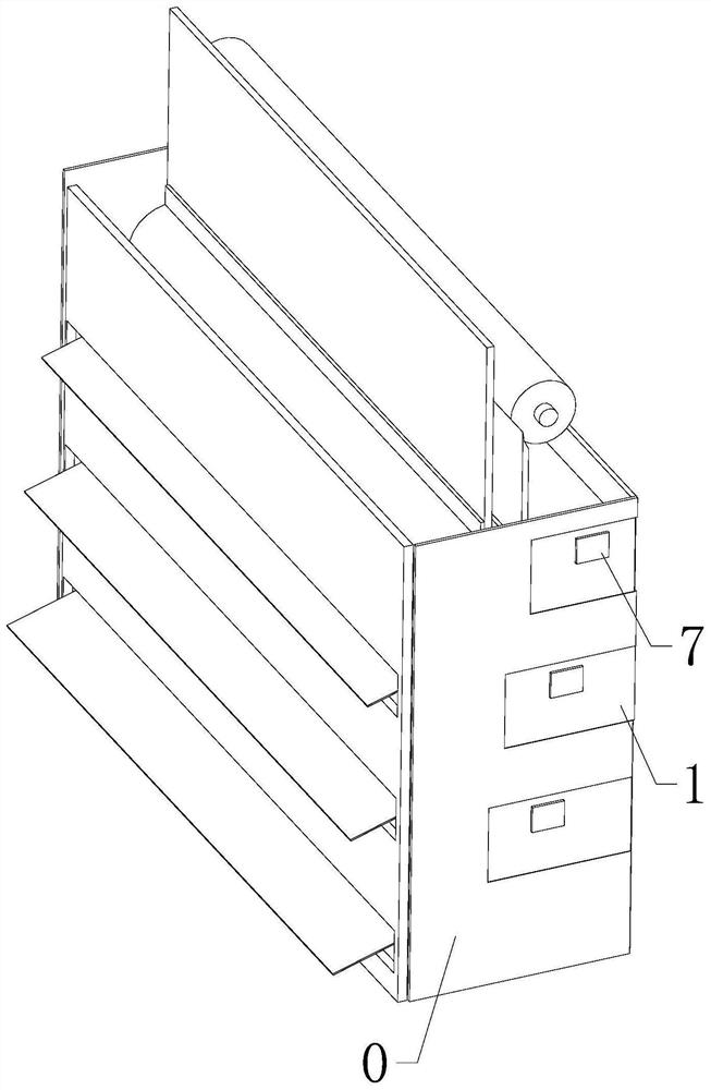
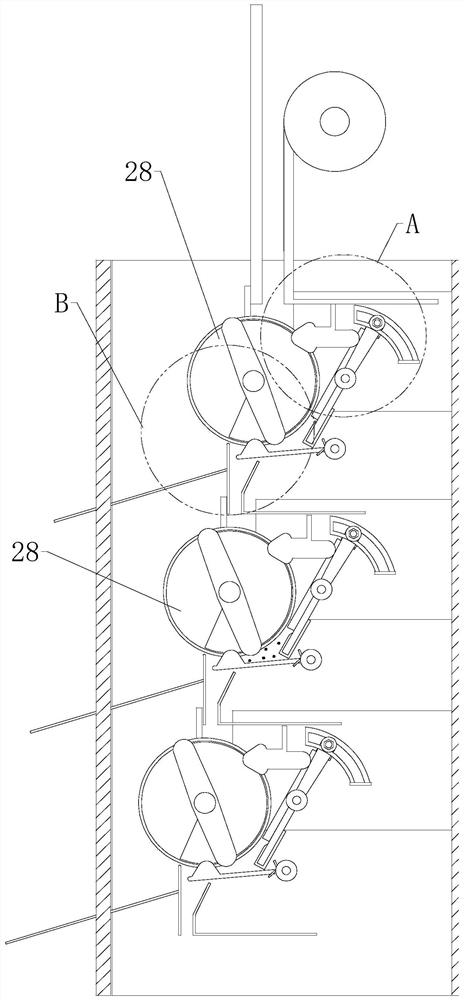
The invention relates to the field of manganese ore beneficiation, in particular to a low-grade manganese carbonate polymetallic ore multistage beneficiation device which comprises a magnetic separation box, and a plurality of horizontal magnetic separation rollers arranged at intervals from top to bottom. An inclined first bouncing board is arranged beside each magnetic separation roller, and a second bouncing board is arranged below each magnetic separation roller. One side of the first bouncing board directly faces the magnetic separation roller, the rotating direction of the magnetic separation roller always faces the clockwise direction of the first bouncing board, and transmission arms are arranged at the two ends of the magnetic separation roller respectively. One ends of the transmission arms are coaxially connected with the magnetic separation roller, and the other ends of the transmission arms can be in transmission connection with the first bouncing board and the second bouncing board. The upper half space part, corresponding to the first bouncing space, of the first bouncing board is a bent area, the transmission arms are used for driving the bent area to swing towards the magnetic separation rollers in a reciprocating mode through self bending, the transmission arms are used for driving the lower end of the second bouncing board to swing up and down. According to the present invention, the screening effect of each magnetic separation roller can be improved, and the screening missing probability can be effectively reduced.

Description

technical field [0001] The invention relates to the field of manganese ore beneficiation, in particular to a multi-stage beneficiation device for low-grade manganese carbonate polymetallic ore. Background technique [0002] Manganese ore is one of the main raw materials for ferroalloy factories and steel mills. At present, the grade of manganese ore for industrial use is about 30-35 degrees. However, most of the manganese ore resources in southwest my country are of low grade and high in harmful impurity elements, so they cannot be used directly; the existing The method is to grind the manganese ore to a set particle size, and then carry out multi-stage mineral separation; the existing mineral processing methods are mainly divided into roasting, flotation mineral separation, magnetic separation and gravity separation, roasting, flotation mineral separation and gravity separation for In terms of the environment, they all have certain pollution, which is contrary to the goal of ...

Claims


Application Information

Patent Timeline
Patent Type & Authority Applications(China)
IPC IPC(8): B03C1/12
CPCB03C1/12
Inventor 刘松夏浩李勇军
Owner TONGREN UNIV
Why Eureka
Try Eureka