
Automatic control platform of pipeline anti-corrosion heat-preservation glass fiber laying device

A glass fiber and laying device technology, which is applied in the field of glass fiber installation, can solve the problems of time-consuming and laborious, troublesome painting and increasing the cost of anti-corrosion, etc.

Active Publication Date: 2021-04-30
浙江壹点设计咨询有限公司
View PDF5 Cites 0 Cited by
  • Summary
  • Abstract
  • Description
  • Claims
  • Application Information

AI Technical Summary

Problems solved by technology

[0005] Using glass fiber to wrap the pipe can achieve a good thermal insulation and anti-corrosion effect. However, the existing pipes are generally wrapped with glass fiber manually, which is time-consuming and laborious. For the installed pipes, especially the pipes on the outer wall, it is inconvenient to do it manually. operation, there is a certain security risk
[0006] At the same time, in the process of pipeline anticorrosion work on the construction site, most of the anticorrosion materials are pasted on the pipeline manually to achieve the purpose of anticorrosion. At the same time, the inner wall of the pipeline needs to be treated with antirust. The inner wall is cleaned and then painted to complete the anti-corrosion work. Although the purpose of anti-corrosion work can be achieved manually, the efficiency of manual work is extremely low, which further increases the cost of anti-corrosion;
[0007] Among them, in the process of pre-corrosion treatment of uninstalled pipelines, it is necessary to carry out anti-corrosion treatment on the outside and inside of the pipeline at the same time. Anti-corrosion treatment is carried out on the inside of the pipeline by painting. Because the inside of the pipeline is deep, it is more troublesome to paint and paint, which further reduces the anti-corrosion efficiency in the pipeline.

Method used


Image

  • Automatic control platform of pipeline anti-corrosion heat-preservation glass fiber laying device
  • Automatic control platform of pipeline anti-corrosion heat-preservation glass fiber laying device
  • Automatic control platform of pipeline anti-corrosion heat-preservation glass fiber laying device

Examples


Embodiment 2

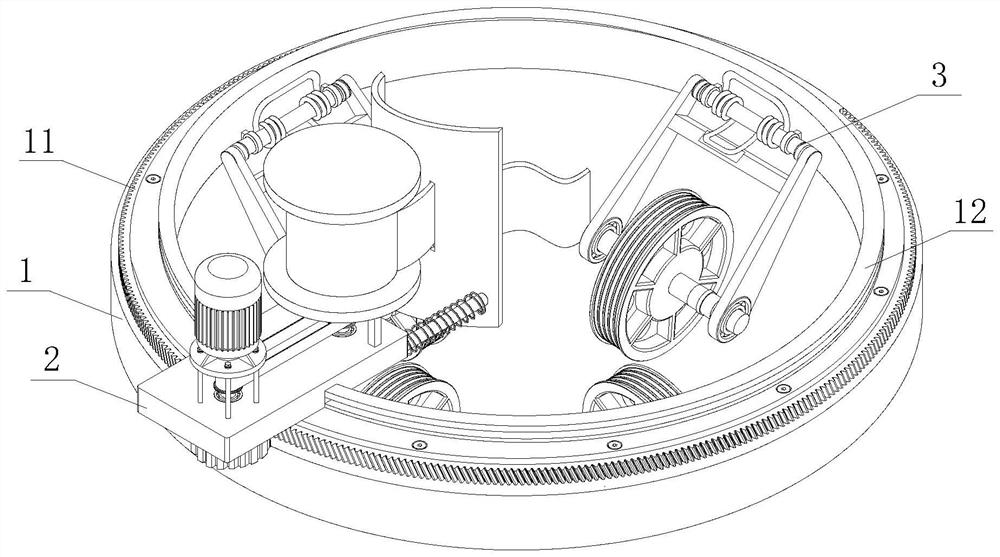
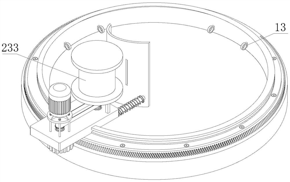
[0051] see Figure 1-Figure 2 , a pipeline anti-corrosion and thermal insulation glass fiber laying device, including an automatic installation cylinder 1, an automatic control platform, and a pipeline 5;

[0052] The upper surface of the automatic installation cylinder 1 is fixedly connected with an annular ring gear 11, the upper surface of the inner side of the annular gear 11 is fixedly connected with a limit slip ring 12, and the limit slip ring 12 is movably connected with a moving plate 2, and the inner wall of the automatic installation cylinder 1 The upper equidistant is connected with fixed suspension ring 13, and rotating wheel frame 3 is installed on the fixed suspension ring 13.

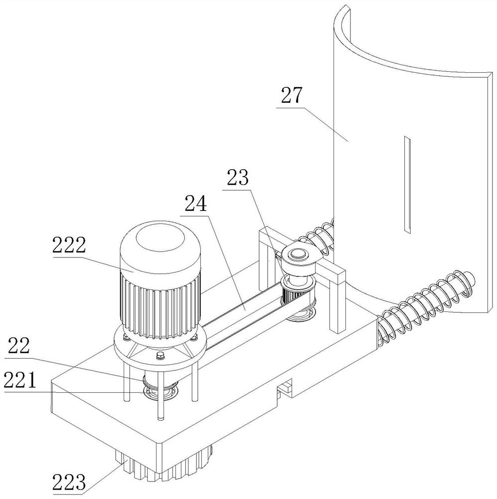
[0053] see Figure 3-Figure 5 , both ends of the moving plate 2 are provided with mounting holes 21, the first pulley 22 and the second pulley 23 are respectively connected by bearings in the mounting holes 21, and the transmission belt 24 is passed between the first pulley 22 and the s...


PUM


Abstract

The invention discloses an automatic control platform of a pipeline anti-corrosion heat-preservation glass fiber laying device. The automatic control platform comprises a fixing base, a first fixing frame, a second fixing frame, a driving module and a control machine body, wherein the first fixing frame and the second fixing frame are separately and fixedly arranged on the fixing base, the driving module is arranged between the first fixing frame and the second fixing frame, the first fixing frame is provided with a first supporting shaft capable of sliding in a telescopic mode, the second fixing frame is provided with a second supporting shaft capable of sliding in a telescopic mode, the first supporting shaft and the second supporting shaft are connected together in a butt joint mode after sliding, the control machine body slides on the first supporting shaft and the second supporting shaft, the interior of a pipeline can be cleaned and painted through sliding of the control machine body, then anti-corrosion operation is completed, the anti-corrosion efficiency of the pipeline is greatly improved, and the anti-corrosion cost is reduced.

Description

technical field [0001] The invention relates to the technical field of glass fiber installation, in particular to an automatic control platform of a pipe anticorrosion and heat preservation glass fiber laying device. Background technique [0002] Pipeline anticorrosion refers to measures to slow down or prevent pipelines from being corroded and deteriorated under the chemical and electrochemical action of internal and external media or by microbial metabolic activities. Protection technology to avoid pipelines from being corroded by soil, air and conveying media (oil, natural gas, etc.). Most of the pipelines for transporting oil and gas are located in complex soil environments, and the transported media are mostly corrosive, so the inner and outer walls of the pipelines may be corroded. Once the pipeline is corroded and perforated, it will cause oil and gas leakage, which will not only interrupt the transportation, but also pollute the environment, and may even cause fire ...

Claims


Application Information

Patent Timeline
IPC IPC(8): B05B13/06B05B15/00B05B16/20B65B33/02B08B9/047B08B9/043
CPCB05B13/0636B05B15/00B08B9/0433B08B9/047B65B33/02B05B16/20
Inventor 于蕾于德永
Owner 浙江壹点设计咨询有限公司
Learn More