Surface treatment device for hardware tool after forming

A technology for hardware tools and processing equipment, applied in metal material coating process, liquid chemical plating, coating and other directions, can solve the problems such as alloy catalytic liquid cannot flow and soak, affect sleeve anti-corrosion treatment effect, and low anti-corrosion treatment efficiency.

Inactive Publication Date: 2020-10-30
张秋鹏
View PDF0 Cites 0 Cited by
  • Summary
  • Abstract
  • Description
  • Claims
  • Application Information

AI Technical Summary

Problems solved by technology

[0005] The invention can solve the problem that the existing sleeve surface anti-corrosion treatment equipment cannot make each surface of the sleeve contact with the alloy catalyst liquid when the sleeve is thrown into the alloy catalyst liquid pool, and cannot make each surface of the sleeve evenly contact with the alloy catalyst through rotation. Liquid contact, affecting the anti-corrosion treatment effect of the sleeve, can also solve the existing sleeve surface anti-corrosion treatment equipment. Good support prevents the alloy catalytic liquid from flowing and soaking to all sides of the sleeve, resulting in low efficiency of anti-corrosion treatment and poor anti-corrosion effect

Method used


Image

  • Surface treatment device for hardware tool after forming
  • Surface treatment device for hardware tool after forming
  • Surface treatment device for hardware tool after forming

Examples


Embodiment Construction

[0027] The embodiments of the present invention will be described in detail below with reference to the accompanying drawings, but the present invention can be implemented in many different ways defined and covered by the claims.

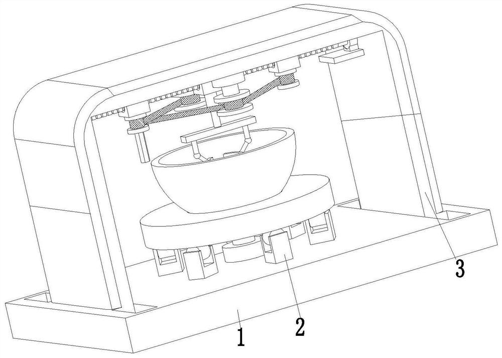
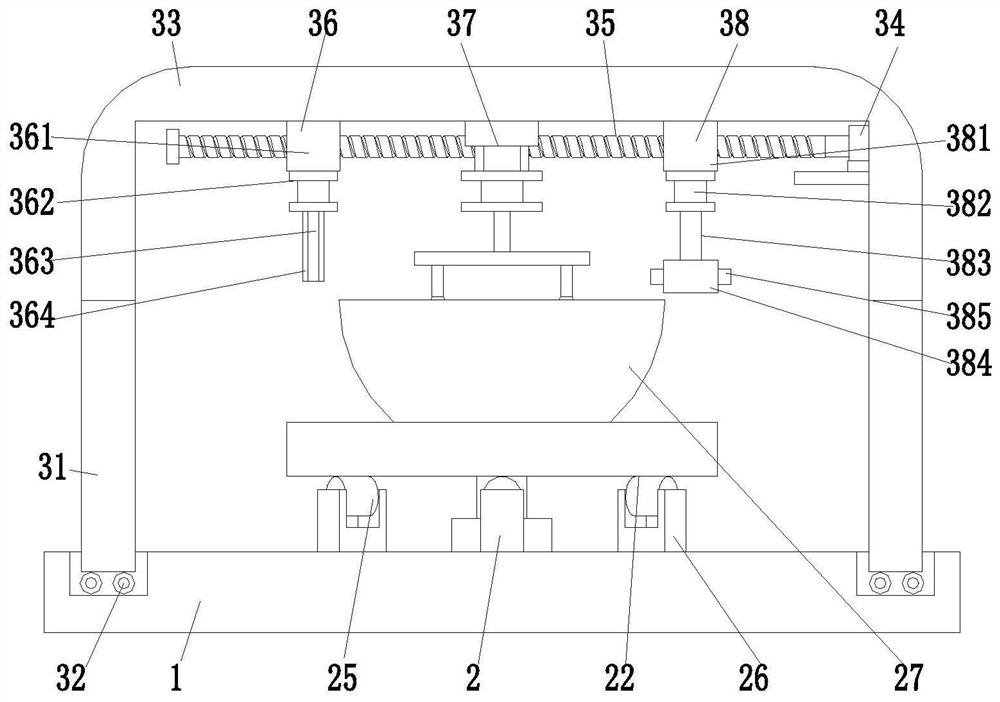
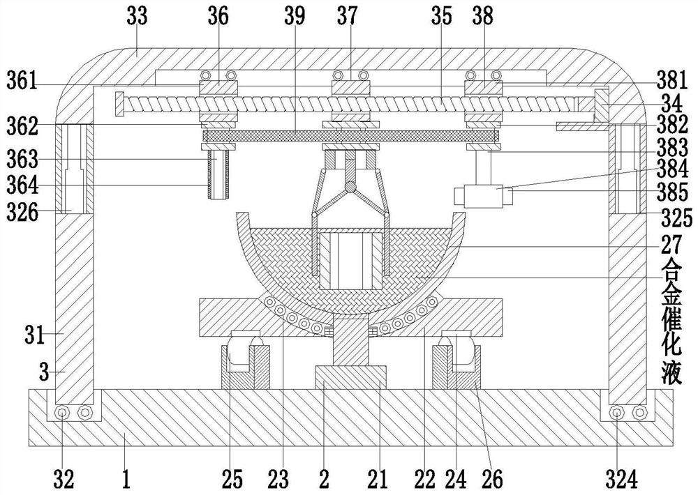
[0028] Such as Figure 1 to Figure 6 As shown, a surface treatment equipment for hardware tools after molding, including a base plate 1, a soaking device 2 and a clamping device 3, the soaking device 2 is installed in the middle of the base plate 1, and chutes are provided at both ends of the base plate 1, inside the chute A clamping device 3 is installed by sliding fit, and the clamping device 3 is located above the soaking device 2 .

[0029] The soaking device 2 includes a rotating motor 21, a disc seat 22, a circular groove 23, an arc chute 24, a rolling wheel 25, a rolling frame 26 and a soaking pool 27, and the rotating motor 21 is installed through a motor base In the middle part of the upper end surface of the bottom plate 1, the output sha...


PUM


Abstract

The invention relates to a surface treatment device for a hardware tool after forming. The surface treatment device comprises a bottom plate, a soaking device and clamping devices, wherein the soakingdevice is arranged in the middle of the bottom plate; sliding grooves are formed in the two ends of the bottom plate; the clamping devices are arranged in the sliding grooves in a sliding fit mode; and the clamping devices are positioned above the soaking device. According to the surface treatment device, the problems that according to existing sleeve surface anti-corrosion treatment device, a sleeve is thrown into an alloy catalyst liquid pool, so that all surfaces of the sleeve cannot be in contact with alloy catalyst liquid, all the surfaces of the sleeve cannot be in uniform contact withthe alloy catalyst liquid through rotation, the anti-corrosion treatment effect of the sleeve is influenced, the sleeve cannot be quickly clamped out when the sleeve soaking anti-corrosion treatment is completed, the sleeve cannot be well supported aiming at the hexagonal structure in the sleeve, so that the alloy catalyst liquid cannot flow to soak all the surfaces of the sleeve, the anti-corrosion treatment efficiency is low, and the anti-corrosion effect is poor can be solved.

Description

technical field [0001] The invention relates to the technical field of hardware anticorrosion, in particular to a surface treatment equipment for hardware tools after forming. Background technique [0002] Hardware refers to the tools obtained by processing and casting gold, silver, copper, iron, tin and other metals, which are used to fix things, process things, decorate and other tools. As a commonly used sleeve in hardware, after casting, it is necessary to do anti-corrosion treatment on the surface and inside of the sleeve, otherwise the sleeve is prone to corrosion and rust after long-term use, which will affect its service life. In daily life, our common metal surface anti-corrosion methods include impressed current electroplating method, surface conversion, and alloy catalytic solution. According to our understanding, the metal surface anti-corrosion method has great environmental pollution, and the technical effect needs to be improved; the cost of surface conversion...

Claims


Application Information

Patent Timeline
IPC IPC(8): C23C18/18
CPCC23C18/1632C23C18/1824
Inventor 张秋鹏
Owner 张秋鹏
Why Eureka
Try Eureka