Bending machine with accurate and controllable bending
A technology of a bending machine and a bending mechanism, which is applied in the field of bending machines, can solve the problems that the processing shape of the sheet cannot meet the processing requirements, increase the production and processing cost, reduce the production efficiency, etc., so as to improve the processing efficiency and economic benefits, guarantee the Processing effect, effect of reducing production cost
- Summary
- Abstract
- Description
- Claims
- Application Information
AI Technical Summary
Problems solved by technology
Method used
Image

Examples
Embodiment
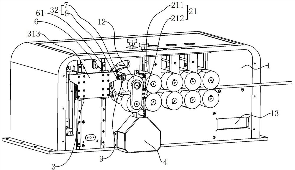
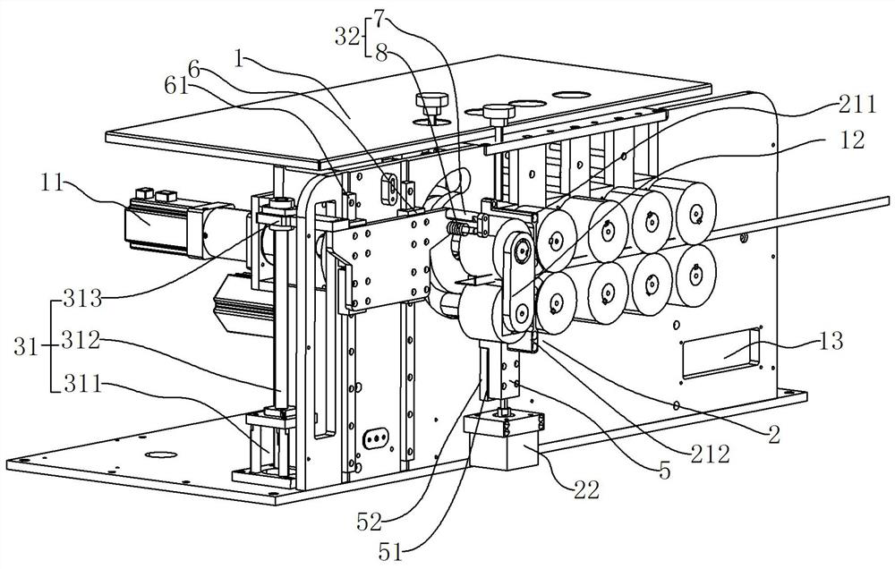
[0035] refer to Figure 1-Figure 2, a bending machine with precise and controllable bending, comprising a frame 1, a power mechanism 11, a bending mechanism 12, a control mechanism 13, an entry limiting mechanism 2 and an output limiting mechanism 3 are arranged on the frame 1, and the bending mechanism 12 is located between the entry limiting mechanism 2 and the output limiting mechanism 3, the control mechanism 13 is electrically connected to the power mechanism 11, the power mechanism 11 drives the bending mechanism 12 to operate, and the control mechanism 13 is electrically connected to the entry limiting mechanism 2 and the output limiting mechanism 3 respectively. sexual connection. According to the material and processing requirements of the plate to be processed, the operator controls the action of the bending mechanism 12, the entry limit mechanism 2 and the limit mechanism 3 through the control mechanism 13 and the power mechanism 11. Before the plate is sent to the ...
PUM
 Abstract
Description
Claims
Application Information
 - Generate Ideas
- Intellectual Property
- Life Sciences
- Materials
- Tech Scout
- Unparalleled Data Quality
- Higher Quality Content
- 60% Fewer Hallucinations
Browse by: Latest US Patents, China's latest patents, Technical Efficacy Thesaurus, Application Domain, Technology Topic, Popular Technical Reports.
© 2025 PatSnap. All rights reserved.Legal|Privacy policy|Modern Slavery Act Transparency Statement|Sitemap|About US| Contact US: help@patsnap.com