Supercharge Your Innovation With Domain-Expert AI Agents!

A laser cutting process for fuel tank blanking

A laser cutting and fuel tank technology, applied in laser welding equipment, applications, manufacturing tools, etc., can solve the problems of severe reaction, inability to ensure smooth section, and achieve uniform temperature, consistency, and cutting quality.

Active Publication Date: 2022-06-21
无锡市祁丰钣金有限公司
View PDF0 Cites 0 Cited by
  • Summary
  • Abstract
  • Description
  • Claims
  • Application Information

AI Technical Summary

Problems solved by technology

[0004] Aiming at the deficiencies of the existing technology, the invention discloses a laser cutting process for fuel tank blanking, in order to solve the problems in the prior art that oxygen participates in the combustion during the laser cutting process, which makes the high temperature lead to a violent reaction and cannot ensure a smooth cross section.

Method used


Image

  • A laser cutting process for fuel tank blanking
  • A laser cutting process for fuel tank blanking
  • A laser cutting process for fuel tank blanking

Examples


no. 1 example

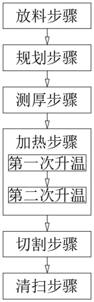
[0072] Include the following steps:

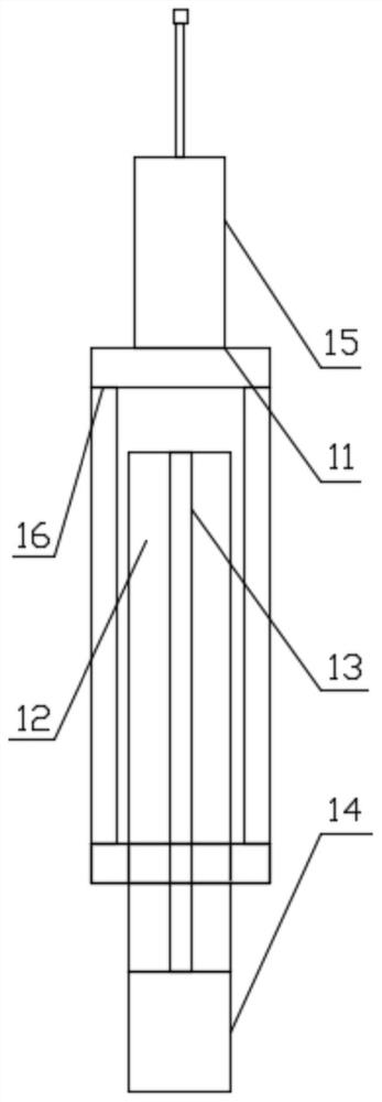
[0073] The discharging step: placing the raw material on the cutting table; several first measuring devices 11 are arranged in parallel on the cutting table; the first measuring device 11 is used to measure the height of the lower surface of the raw material;

[0074] Planning steps: use a camera to shoot the upper surface of the raw material; calculate the laser cutting path according to the shooting map;

[0075] Thickness measurement step: using a second measuring mechanism to measure the height of the upper surface of the raw material; moving the second measuring mechanism along the laser cutting path; obtaining the thickness of the raw material at multiple positions on the laser cutting path. The thickness of the raw material is 3.95 mm, 3.97 mm, 4.02 mm, and 4.05 mm.

[0076] A heating step is also included between the thickness measurement step and the cutting step; the heating step specifically includes:

[0077] The first heatin...

no. 2 example

[0083] Include the following steps:

[0084] Unloading step: Put the raw material on the cutting table. A plurality of first measuring devices 11 are arranged in parallel on the cutting table. The first measuring device 11 is used to measure the height of the lower surface of the raw material.

[0085] Planning steps: Use a camera to shoot the upper surface of the raw material. Calculate the laser cutting path based on the captured image.

[0086] Thickness measurement step: use the second measurement mechanism to measure the height of the upper surface of the raw material. The second measurement mechanism moves along the laser cutting path. Obtain the thickness of the raw material at multiple locations along the laser cutting path. The range of raw material thickness is 3.95mm, 4.01mm, 3.96mm, 4.04mm.

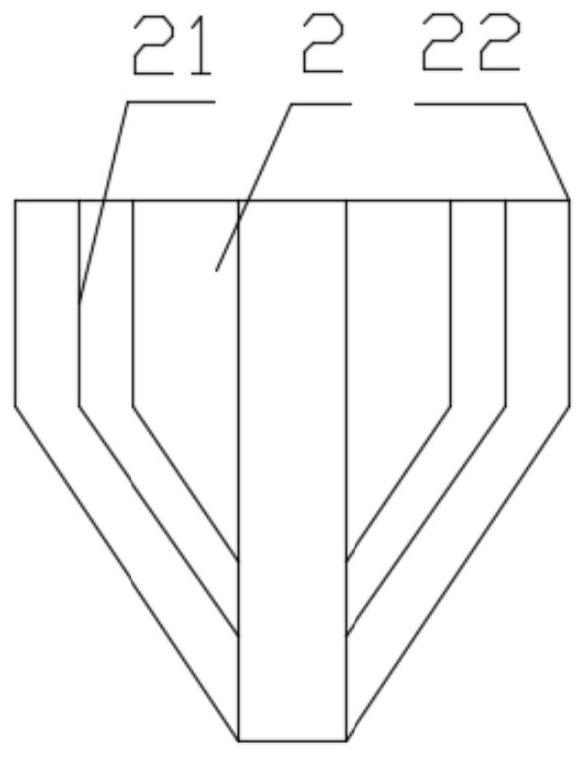
[0087]Cutting step: Use cutter 2 to emit laser to cut the raw material. The power of cutter 2 is 3000W, 3600W, 3100W and 3900W. A first nozzle 21 is provided around th...

no. 3 example

[0091] Include the following steps:

[0092] Unloading step: Put the raw material on the cutting table. A plurality of first measuring devices 11 are arranged in parallel on the cutting table. The first measuring device 11 is used to measure the height of the lower surface of the raw material.

[0093] Planning steps: Use a camera to shoot the upper surface of the raw material. Calculate the laser cutting path based on the captured image.

[0094] Thickness measurement step: use the second measurement mechanism to measure the height of the upper surface of the raw material. The second measurement mechanism moves along the laser cutting path. Obtain the thickness of the raw material at multiple locations along the laser cutting path. The range of raw material thickness is 3.97mm, 4.04mm, 4.05mm, 3.96mm.

[0095] A heating step is also included between the thickness measurement step and the cutting step; the heating step specifically includes:

[0096] The first temperatu...


PUM

PropertyMeasurementUnit
thicknessaaaaaaaaaa

Abstract

The invention relates to a laser cutting process for fuel tank blanking; it is characterized in that: the step of discharging material; placing the raw material on the cutting table; the first measuring device is used to measure the height of the lower surface of the raw material; the planning step; using a camera mechanism to photograph the raw material Upper surface; calculate the laser cutting path according to the photograph; thickness measurement step; use the second measuring mechanism to measure the height of the upper surface of the raw material; the second measuring mechanism moves along the laser cutting path; obtain the thickness of the laser cutting path of the raw material; cutting step; use a cutter Laser cutting raw materials; a first nozzle is arranged around the cutter; the first nozzle sprays a combustion-supporting gas; a second nozzle surrounds the first nozzle; the second nozzle sprays an inert gas; cleaning steps; Move along the laser cutting path. It solves the problems caused by the existing scheme that oxygen participates in the combustion during the laser cutting process, which makes the high temperature lead to violent reaction and cannot guarantee the smooth cross section.

Description

technical field [0001] The invention relates to a cutting process, in particular to a laser cutting process for fuel tank blanking. Background technique [0002] Generally, the laser beam is irradiated on the surface of the material through the nozzle, the material reaches a molten state after absorbing energy, and the auxiliary gas blows the molten liquid material away, and the melting point area gradually moves with the cutting direction to produce a continuous slit, which is laser cutting. . The high power density laser beam is used to irradiate the material to be cut, so that the material is quickly heated to the vaporization temperature, and evaporates to form a hole. As the beam moves to the material, the hole continuously forms a narrow slit to complete the cutting of the material. Oxygen is used for assisted cutting in the laser cutting process, but the existing solution leads to a rough cut section, and how to solve this problem becomes crucial. [0003] In the ex...

Claims


Application Information

Patent Timeline
Patent Type & Authority Patents(China)
IPC IPC(8): B23K26/38B23K26/14B23K26/03B23K26/60B23K26/142
CPCB23K26/38B23K26/14B23K26/032B23K26/60B23K26/142B23K2101/12
Inventor 高宇超
Owner 无锡市祁丰钣金有限公司
Features
  • R&D
  • Intellectual Property
  • Life Sciences
  • Materials
  • Tech Scout
  • Unparalleled Data Quality
  • Higher Quality Content
  • 60% Fewer Hallucinations
Learn More