Tool clamp for machining single-shaft shredder blade by lathe

A technology of lathe processing and tooling and fixtures, which is applied in the direction of metal processing machinery parts, manufacturing tools, metal processing equipment, etc., and can solve problems such as workpiece tilt and offset, affecting device processing accuracy, and reducing device practicability

Inactive Publication Date: 2021-04-30
南京华鑫机械刀具制造有限公司
View PDF7 Cites 0 Cited by
  • Summary
  • Abstract
  • Description
  • Claims
  • Application Information

AI Technical Summary

Problems solved by technology

[0004] The object of the present invention is to provide a tooling fixture for lathe processing single-shaft shredder blades, to solve the existing tooling fixtures for lathe processing single-shaft shredder blades proposed in the background technology, usually in the When the blade of the single-shaft shredder is proces...

Method used


Image

  • Tool clamp for machining single-shaft shredder blade by lathe
  • Tool clamp for machining single-shaft shredder blade by lathe
  • Tool clamp for machining single-shaft shredder blade by lathe

Examples


Embodiment 1

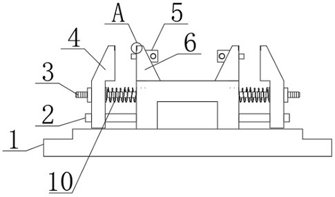
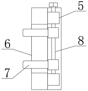
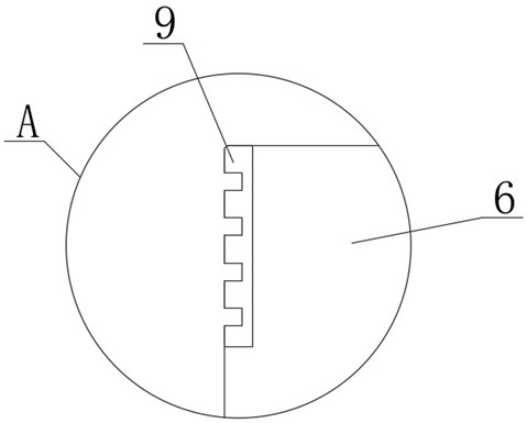
[0024] see figure 1 , figure 2 , image 3 with Figure 4 , the present invention provides a technical solution: a tooling fixture for lathe processing single-axis shredder blades, including a fixture seat 1, an integrated clamp block 6 is provided at the top edge of the fixture seat 1, and the fixture seat 1 Both sides of the top are connected with clamp arms 4, and the top sides of the fixture seat 1 are fixedly equipped with fixed rods 3 and limit rods 2. The block 6 is provided with an integrated fixed seat 5, the fixed seat 5 is screwed and installed with a screw rod 8, and the screw rod 8 is rotated with a horizontal clamping rod 7, and the inner side of the clamping block 6 is provided with a through groove, and the horizontal clamping rod One end of 7 is installed in the through groove. When the fixture is working, the workpiece can be clamped and installed stably by the horizontal clamp rod 7 and the clamp arm 4 to ensure the stability of the workpiece and prevent ...

Embodiment 2

[0027] see figure 1 , figure 2 , image 3 , Figure 4 with Figure 5 , the present invention provides a technical solution: a tooling fixture for lathe processing single-axis shredder blades, including a fixture seat 1, an integrated clamp block 6 is provided at the top edge of the fixture seat 1, and the fixture seat 1 Both sides of the top are connected with clamp arms 4, and the top sides of the fixture seat 1 are fixedly equipped with fixed rods 3 and limit rods 2. The arm 4 is provided with an integrated fixed seat 5, the fixed seat 5 is screwed and installed with a screw rod 8, and the screw rod 8 is rotated with a horizontal clamping rod 7, the inner side of the clamp arm 4 is provided with a through groove, and the horizontal clamping rod One end of 7 is installed in the through groove. When the fixture is working, the workpiece can be clamped and installed stably by the horizontal clamp rod 7 and the clamp arm 4 to ensure the stability of the workpiece and preven...


PUM


Abstract

The invention discloses a tool clamp for machining single-shaft shredder blade by a lathe. The tool clamp comprises a clamp base, an integrated clamping block is arranged at the edge of the top of the clamp base, clamping arms are connected to the two sides of the top of the clamp base, a fixing rod and a limiting rod are fixedly arranged on the two sides of the top of the clamp base, the clamping arms are arranged on the limiting rods and the fixing rods in a penetrating mode, and an integrated fixing base is arranged on the clamping block. When the clamp is used and installed, a workpiece is clamped on the clamp in the opposite direction, in the machining process, the workpiece possibly inclines and deviates, and the machining precision of the workpiece is affected, and when the clamp works, the workpiece can be stably clamped and installed through matched clamping of transverse clamping rods and the clamping arms, the stability of the workpiece is guaranteed, and the workpiece is prevented from inclining and deviating in the machining process; and a spring is arranged on the fixing rod of the device, and after the clamping arms are installed, when the clamping arms are disassembled and assembled, the clamping arms can be automatically reset through the spring, and the workpiece is conveniently disassembled and assembled.

Description

technical field [0001] The invention belongs to the technical field of tooling fixtures, and in particular relates to a tooling fixture used for lathe processing single-axis shredder blades. Background technique [0002] A shredder is a machine used for fine crushing, which is generally used to process unprocessed raw materials or scraps to make them smaller in size. A representative example is to shred plastic or rubber scraps and use them as raw materials to melt and granulate them to remake plastic bottles, tires or trash cans, etc. The shredder is used in the plastic recycling industry, and is often used for the crushing of waste large-diameter PE plastic pipes, bundled plastic films, large stacks of plastic sheets and machine head materials. The application of the shredder generally includes: shredding unqualified products into smaller pieces for recycling; reducing the volume of unprocessed raw materials for mixing with other materials, etc. Fixture: A device used to...

Claims


Application Information

Patent Timeline
IPC IPC(8): B23Q3/06
CPCB23Q3/06B23Q3/067
Inventor 赵攀
Owner 南京华鑫机械刀具制造有限公司
Why Eureka
Try Eureka