Multi-stage series connection type distributed control system of robot

A control system and serial technology, applied in the direction of comprehensive factory control, manipulators, manufacturing tools, etc., can solve the problems of inability to adjust circuit boards, inconvenient installation of circuit boards, etc., and achieve the effect of being easy to fully utilize, easy to operate, and ensure stability

Active Publication Date: 2021-04-30
上海纳深机器人有限公司
7 Cites 1 Cited by

AI-Extracted Technical Summary

Problems solved by technology

[0005] The invention provides a robot multi-stage serial distributed control system, which solves the ...

Method used

By disassembling the shielding plate 8 and the housing 1, pulling the shielding plate 8 can drive the operating rod 9 and the sliding plate 2 to move outwards, and then the circuit board can be driven by two driving structures 3 and two connecting assemblies 4 5 moves outward, which is convenient for staff to maintain, replace or clean the circuit board 5 .
By manually rotating the circular plate 38, the rotating shaft 37 can be driven to rotate, the second roller 33 can be driven to rotate, and the rotation of the second roller 33 can cooperate with the first roller 32 to drive the transmission belt 34 to rotate, and then can Drive the driving rod 35 to move up and down, through the up and down movement of the two driving rods 35, the two connecting plates 36 can be driven to move up and down, and then the circuit board 5 can be driven to adjust the height, and then the two second T-shaped blocks 47 can be moved downward , by inserting the two second T-shaped blocks 47 into the corresponding slots 39, thereby clamping the circular plate 38, and then clamping the circuit board 5 after moving up and down, so as to ensure its stability;
By the rotation of the second roller 33, the first roller 32 can be used to drive the drive belt 34 to rotate, and then the driving rod 35 can be driven to move up and down, and the two connecting plates 36 can be driven by the movement of the two driving rods 35 up and down. Move up and down, and then can drive the circuit board 5 to adjust the height, and then move the two second T-shaped blocks 47 downwards, and insert the two second T-shaped blocks 47 into the corresponding slots 39, so that the circular plate 38 Carry out clamping, and then clamp the circuit board 5 after moving up and down, to ensure its stability, through the setting of two driving structures 3, the height of the circuit board 5 can be adjusted, and the housing can be adjusted through the circuit board 5 1 is adjusted to facilitate the full use of the upper half space and the lower half space of the circuit board 5, and to facilitate the induction of the wires connected to the circuit board 5.
By the rotation of the stopper 44, the circuit board 5 can be clamped by the elastic clamping pad 45, so that the circuit board 5 and the connecting plate 36 are fixed, and then the second T is moved to the position of the clamping block 46 The block 47 clamps the clamping block 46 through the second T-shaped block 47, and through the adsorption of the second T-shaped block 47 to the clamping block 46, thereby ensuring the stability of the installation of the circuit board 5, through two connections The component 4 can quickly install and clamp the circuit board 5, and does not require a large number of auxiliary tools for installation, and is easy to operate;
Circuit board 5 can be installed and clamped quickly by two connecting assemblies 4, and does not need a large amount of auxiliary tools to install, and simple to operate, easy to operate, and by the setting of two driving s...

Abstract

The invention provides a multi-stage series connection type distributed control system of a robot. The system comprises a shell, a sliding plate is slidably connected to the bottom of the inner wall of the shell, driving structures are fixedly connected to the two sides of the top of the sliding plate, the two driving structures are slidably connected to the two sides of the inner wall of the shell correspondingly, and a circuit board is installed between the opposite sides of the two driving structures through connecting assemblies. According to the multi-stage series connection type distributed control system of the robot, the circuit board can be rapidly installed and clamped through the two connecting assemblies, a large number of auxiliary tools are not needed for installation, operation is easy and convenient, and the height of the circuit board can be adjusted through the arrangement of the two driving structures; and an internal space of the shell can be adjusted through the circuit board, so that the upper half space and the lower half space of the circuit board are fully utilized, and wires connected with the circuit board can be collected conveniently.

Application Domain

Total factory controlManipulator

Technology Topic

Interior spaceSlide plate +3

Image

  • Multi-stage series connection type distributed control system of robot
  • Multi-stage series connection type distributed control system of robot
  • Multi-stage series connection type distributed control system of robot

Examples

  • Experimental program(1)

Example Embodiment

[0029]The present invention will be further described below with reference to the accompanying drawings and embodiments.
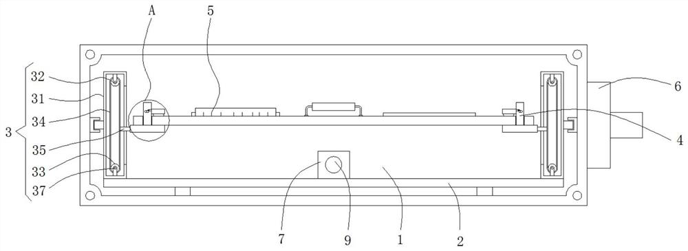
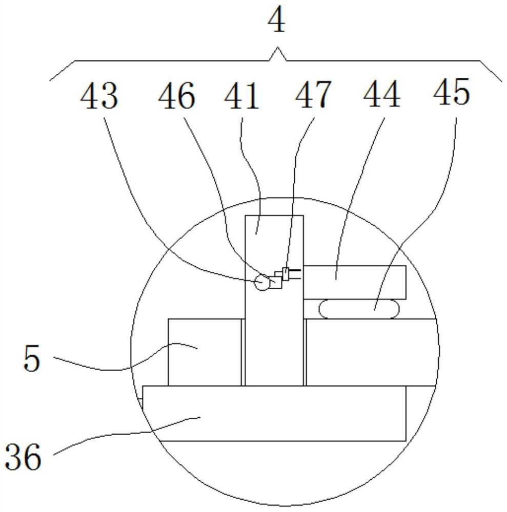
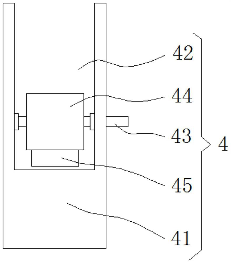
[0030]Please refer tofigure 1 ,figure 2 ,image 3 ,Figure 4 withFigure 5,among them,figure 1 A structural diagram of a preferred embodiment of the robot multi-stage series formula control system provided by the present invention;figure 2 forfigure 1 Shownfigure 1 Local enlargement map at the middle A;image 3 forfigure 2 Structure side elevational view of the connection block shown;Figure 4 forfigure 1 The structure of the driver shown;Figure 5forfigure 1 The structure of the housing shown. Robot multi-level series formula control system includes:
[0031]The housing 1, the bottom slide of the inner wall of the housing 1 is slidably coupled with a sliding plate 2, and both sides of the top of the slide plate 2 are fixedly connected to the drive structure 3, and the two drive structures 3 are slidably connected to the locate. On both sides of the inner wall of the housing 1, a circuit board 5 is mounted between the two of the drive structures 3 and the opposite side of the drive structure 3;
[0032]The drive structure 3 includes a driving box 31 that is fixed to the top of the slide plate 2, and the top of the driver box 31 is rotated through the support frame having a first roller 32, the drive The bottom of the inner wall of the box 31 is rotated by a support frame having a second roller 33, and the outer surface of the second roller 33 is transmitted through the outer surface of the first roller 32 through the transmission belt 34, and the outer surface of the transmission belt 34 is fixed. The drive rod 35 is connected, and one end of the drive lever 35 penetrates the driving case 31 and extends to the outside of the driving case 31, the drive rod 35 extends to one end of the outer end of the driving case 31 fixed connection Board 36;
[0033]The bottom of the two connection assemblies 4 is respectively disposed at the top of the two connecting plates 36;
[0034]The two connection assembly 4 can be quickly mounted, and no large amount of auxiliary tool is required, and the operation is simple, easy to operate, and through the setting of the two drive structure 3, the circuit board 5 can be The height is adjusted, and the internal space of the housing 1 can be adjusted by the circuit board 5, which is convenient for sufficient use of the upper half space and the lower half space of the circuit board 5, which is convenient for the lead in which the wire plate 5 is connected;
[0035]The robot multi-stage series formula control system consists of multi-line data receiving end, downlink data transmitting end, uplink data receiving end, downlink data transmitting end, uplink data receiving end, uplink data transmitting end, flow control receiving end, uplink data transmitting end, flow control receiving end The arithmetic chip is connected in series, and is connected by a control chip to the sequence of the zippe calculation chip to form a series communication system structure, while. Using the designed downlink, uplink communication protocol, and through the flow control receiving end, the flow control signal of the flow control transmitted transmitted transmitted data is used to transmit the transmitted data of each arithmetic chip. The line structural design of the present invention is low, so that its production cost is lower, and at the same time, the interference of the upper and lower line communication data of each of the computational chips is eliminated, and each arithmetic chip can be properly received and Send data while supporting both broadcast and unicast, taking into account efficient and flexible.
[0036]The axial core of the second roller 33 is fixedly connected to the rotation shaft 37, and one end of the rotation shaft 37 penetrates the front side of the driving case 31, the rotation shaft 37 extends to the front surface of the driver box 31 fixed connection with a circle. The plate 38, the outer surface of the circular plate 38 is opened with a card slot 39;
[0037]The number of card slots 39 is four, which is convenient for the insertion of the first T-type block 310, and rotates the circular plate 38 and the rotation shaft 37 through the card slot 39, and thereby tighter the second roller 33, thereby ensuring the circuit board. 5 Highly adjusted stability.
[0038]The front surface of the driver box 31 is slid with a first T type block 310, and the bottom of the first T-type block 310 penetrates the card slot 39 and extends to the interior of the card slot 39.
[0039]The connecting assembly 4 includes a connecting block 41, and there is a hidden groove 42 between the two sides of the connecting block 41, and the front and back surfaces of the inner wall of the hidden groove 42 are rotated between the active rod 43;
[0040]The setting of the hidden groove 42 is convenient for the shrinkage hidden of the limit block 44, which is convenient for the installation of the circuit board 5.
[0041]The outer surface of the movable rod 43 is fixed to the finite block 44, and the bottom portion of the limit block 44 is fixedly connected to the elastic clamping pad 45;
[0042]The set block 44 is provided for moving the positional movement of the elastic clamp pad 45 to the circuit board 5, so that the circuit board 5 can be tightened.
[0043]One end of the movable rod 43 penetrates the front surface of the connecting block 41, the movable rod 43 extends to the outer surface of one end of the front side of the connecting block 41 fixedly coupled with a cardinal block 46, and the front side of the connecting block 41 One side fixed connection has a second T-block 47;
[0044]The setting of the second T type block 47 is used to tighten the rotating limit block 44, thereby ensuring the stability of the limit block 44 rotates the movement.
[0045]The second T-shaped block 47 employs a magnetic material that uses a metal iron material;
[0046]The magnetic material is employed by the second T type block 47, and a metal ferrous material is employed by the card tension block 46, facilitating the second T-type block 47 to connect with the card tension block 46.
[0047]The top portion of the slide plate 2 is fixedly coupled with a fixing plate 7, and the front surface of the housing 1 is fixedly connected to the block 8;
[0048]The setting of the fixing plate 7 is convenient to connect to the occlusion plate 8 such that the moving plate 8 can be moved, and the fixing plate 7 can be moved to facilitate extraction of the circuit board 5 from the inside of the housing 1.
[0049]The front surface of the fixing plate 7 is fixedly coupled with the operating lever 9, and the other end of the operating lever 9 is fixed to the back surface of the occlusion plate 8;
[0050]By disassembling the occlusion plate 8 with the housing 1, the pulling the shutter 8 can be moved away from the operation lever 9 and the slide plate 2, and can be moved through two drive structures 3 and the two connecting assemblies 4 outward. Sports, it is convenient for staff to repair, replace or clean the circuit board 5.
[0051]A connection end 6 is provided on one side of the housing 1;
[0052]The connection end 6 is convenient to multi-stage tandem connection with the outside robot.
[0053]The working principle of the robot multi-stage series formula control system provided by the present invention is as follows:
[0054]The two sides of the circuit board 5 that need to be mounted are placed on the two connecting plates 36, and the manual rotation limit block 44 can be manually rotated, and the circuit board 5 can be clamped by the elastic clamp pad 45 by the restricted block 44. The circuit board 5 is fixed to the connecting plate 36, and the second T-block 47 is moved to the position of the tension block 46, and the tension block 46 is tightened by the second T-type block 47, and passes the second T-block. 47 Adsorption of the card tensioner 46 and ensures stability of the mounting of the circuit board 5;
[0055]By manual rotating the circular plate 38, the rotation shaft 37 can be rotated, and the second roller 33 can be rotated, and the rotation of the second roller 33 can be rotated with the first roller 32 to carry out the drive belt 34, so that the drive rod can be driven 35 Movement, through the motion of the two drive rods 35, two connecting plates 36 can be moved up and down, and can also be highly adjusted by moving the circuit board 5, and then motion two second T-block 47, by two The second T-type block 47 is inserted into the card slot 39 of the corresponding position, thereby tighter the circular plate 38, thereby tensioning the circuit board 5 after the up and down movement, ensuring its stability;
[0056]The re-exercise occlusion plate 8 pushes the circuit board 5 to the inside of the housing 1, and the occlusion plate 8 is fixed to the housing by four screws.
[0057]Compared with the related art, the robot multi-stage series formula control system provided by the present invention has the following beneficial effects:
[0058]The circuit board 5 can be clamped by the elastic clamp pad 45 by the resilient clamp pad 45, so that the circuit board 5 is fixed to the connecting plate 36, and the second T-block 47 is moved to the position of the tension block 46. The card tension block 46 is tightened by the second T type block 47, and the adsorption of the card plate 46 is passed through the second T type block 47 to ensure the stability of the circuit board 5, and the two connection assembly 4 can be Quickly install the panel 5, and does not require a large number of accessories to be installed, and the operation is simple, easy to operate;
[0059]The rotation of the second roller 32 can be mounted with the first roller 32 to perform the rotational movement, and can cause the drive rod 35 to move up and down, and through the motion of the two drive rods 35, two connecting plates 36 can be moved up and down, Further, the circuit board 5 can be moved to perform high adjustment, and then the two second T-type block 47 is moved downward, and the disc 38 is inserted into the card slot 39 of the corresponding position by two second T-type block 47 to tighten the circular plate 38. Further, the circuit board 5 after the upper and lower movement is tightened to ensure that the stability is ensured, and the height of the two drive structure 3 can be adjusted, and the inside of the casing 1 can be adjusted by the circuit board 5. The space is adjusted, which is convenient for sufficient use of the upper half space and the lower half space of the circuit board 5, which is convenient for the wires connected to the circuit board 5.
[0060]It is only the embodiments of the present invention, and is not limited to the patent scope of the present invention, and an equivalent structure or equivalent flow transform is used to use the specification of the present invention and the drawings, or use it directly or indirectly in other related technologies. The field is related to the patent protection range of the present invention.

PUM

no PUM

Description & Claims & Application Information

We can also present the details of the Description, Claims and Application information to help users get a comprehensive understanding of the technical details of the patent, such as background art, summary of invention, brief description of drawings, description of embodiments, and other original content. On the other hand, users can also determine the specific scope of protection of the technology through the list of claims; as well as understand the changes in the life cycle of the technology with the presentation of the patent timeline. Login to view more.

Similar technology patents

Intelligent mobile communication terminal and wireless network access method and system thereof

InactiveCN103068066Aeasy to operateImprove network utilization
Owner:GUANGDONG OPPO MOBILE TELECOMM CORP LTD

Classification and recommendation of technical efficacy words

  • easy to operate
  • Guaranteed stability

Lancet device

InactiveUS7303573B2inexpensively mass-producedeasy to operate
Owner:ABBOTT DIABETES CARE INC

Rapid and non-invasive optical detection of internal bleeding

InactiveUS20050065436A1easy to operaterapid and accurate result
Owner:HO WINSTON ZONH +2

A ccd-type colloidal gold immunochromatographic diagnostic test paper quantitative analysis system

InactiveCN102279263AGuaranteed stabilityAddressing Subjective Bias
Owner:杭州顿力医疗器械有限公司

General clamp for abrasive flow polishing of complicated hole surface

InactiveCN104551985AContinuous and stable flowGuaranteed stability
Owner:CHANGCHUN UNIV OF SCI & TECH

Laminated intelligent shock-isolation bearing capable of self-adaptively regulating cutting performance

InactiveCN101586641AGuaranteed stabilityThe interlayer displacement of the isolation layer is small
Owner:WUHAN UNIV OF TECH
Why Eureka
Try Eureka