An Adaptive Clamping Tooling

A clamping tooling and self-adaptive technology, applied in the direction of chucks, manufacturing tools, metal processing equipment, etc., can solve the problems of heavy cylinder weight, large diameter, frequent replacement of clamps, etc., to reduce the chance of clamping deviation , reduce the probability of deviation, and improve the effect of transportation efficiency

Active Publication Date: 2022-04-22
重庆市合川区昌友机械制造有限责任公司
View PDF7 Cites 0 Cited by
  • Summary
  • Abstract
  • Description
  • Claims
  • Application Information

AI Technical Summary

Problems solved by technology

When machining fan gears, the cylinder is first moved to the processing position, and then the gear teeth are processed. However, due to the heavy weight and large diameter of the cylinder, the manual handling efficiency is low, and the labor intensity of the operator is increased.
[0003] In order to reduce the labor intensity of the operator and improve the handling efficiency of the cylinder, the lifting fixture is now used to transport the cylinder, specifically: the cylinder is clamped and then transported to the processing position, but different types of fixtures will be selected for cylinders with different diameters , which in turn leads to frequent replacement of fixtures, which undoubtedly reduces the transportation efficiency of cylinders

Method used


Image

  • An Adaptive Clamping Tooling
  • An Adaptive Clamping Tooling
  • An Adaptive Clamping Tooling

Examples


Embodiment 1

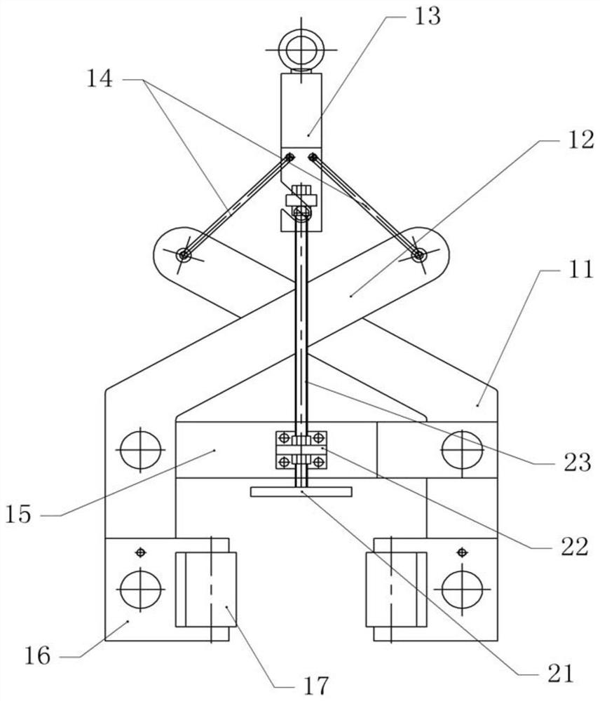
[0036] Basic as attached figure 1 To attach Figure 4 As shown: an adaptive clamping tool, including a hook 13, and a clamping body is arranged below the hook 13. In this embodiment, the clamping body includes a first clamping arm 11 and a second clamping arm 12. The first clamping arm 11 and the second clamping arm 12 are spherically hinged with a suspension rope 14 , and the suspension rope 14 is hinged with the hook 13 .

[0037] The upper crossing of the first clamping arm 11 and the second clamping arm 12 is X-shaped, and a connecting arm 15 is arranged between the first clamping arm 11 and the second clamping arm 12 bottoms, and one end of the connecting arm 15 is connected to the first clamping arm 12. The clamping arm 11 is rotatably connected, the other end of the connecting arm 15 is U-shaped, and the second clamping arm 12 is located between the other U-shaped ends of the connecting arm 15 , and the connecting arm 15 is rotatably connected to the second clamping ar...

Embodiment 2

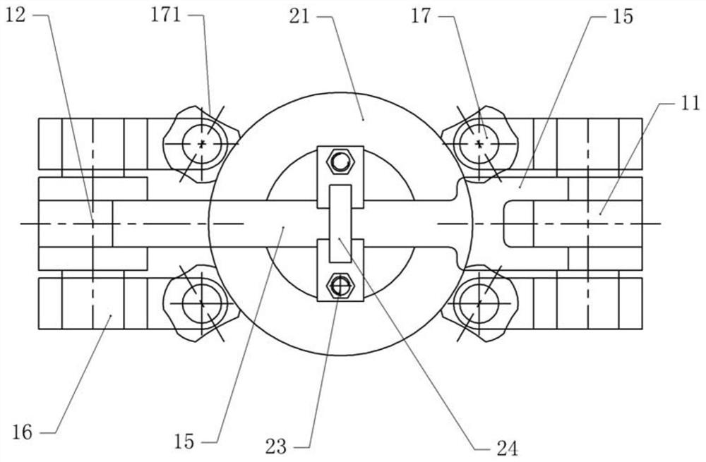
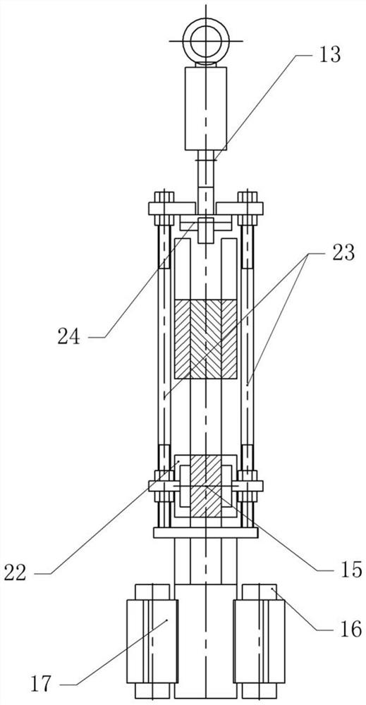
[0043] The difference between embodiment two and embodiment one is that, as attached Figure 5 And attached Image 6 As shown, the clamping member 17 includes a rotating shaft 172 and a clamping portion, and the clamping groove 171 is arranged along the circumferential direction of the clamping portion. The lower part of the rotating shaft 172 is connected to the fixed block 16 in rotation. The rotating shaft 172 is provided with several sliders 173 along its circumference. The elastic part in the example is a spring 175, one end of the spring 175 is welded on the slider 173, the other end of the spring 175 is welded on the rotating shaft 172, and the side of the slider 173 away from the spring 175 has an inclined surface. The fixed block 16 is provided with a plurality of sliding slots 174 , the number of sliding slots 174 is the same as that of the sliding blocks 173 , and the sliding blocks 173 are located in the sliding slots 174 .

[0044] The specific implementation pr...


PUM


Abstract

The invention relates to the technical field of gear processing fixtures, and discloses an adaptive clamping tool, which includes a first clamping arm and a second clamping arm, the first clamping arm and the second clamping arm constitute a clamping body, and the first clamping arm and the second clamping arm form a clamping body. A connecting arm is arranged between a clamping arm and the second clamping arm, one end of the connecting arm is rotatably connected to the first clamping arm, and the other end of the connecting arm is rotatably connected to the second clamping arm; the first clamping arm The lower part of the arm and the second clamping arm is provided with a clamping part, and the clamping part includes a fixed block, on which a number of clamping parts are rotatably connected, and a number of arc-shaped clamping parts are arranged on the clamping part along its circumference. Holding slots, the radians of several holding slots are different; both sides of the connecting arm can be detachably connected with screw rods, a positioning plate is set under the connecting arm, a cross bar is fixed between the upper ends of the two screw rods, and the lower ends of the two screw rods It is fixedly connected with the positioning plate. The invention has a simple structure, can select clamping grooves with different radians to clamp workpieces, and avoids frequent replacement of clamps.

Description

technical field [0001] The invention relates to the technical field of gear processing fixtures, and specifically discloses an adaptive clamping tool. Background technique [0002] The wind turbine gearbox is an important part of the wind turbine. There are many kinds of gears installed in the wind turbine gearbox, mainly cylindrical gears. When machining fan gears, the cylinder is first moved to the processing position, and then the gear teeth are processed. However, due to the heavy weight and large diameter of the cylinder, the manual handling efficiency is low, and the labor intensity of the operator is increased. [0003] In order to reduce the labor intensity of the operator and improve the handling efficiency of the cylinder, the lifting fixture is now used to transport the cylinder, specifically: the cylinder is clamped and then transported to the processing position, but different types of fixtures will be selected for cylinders with different diameters , which in ...

Claims


Application Information

Patent Timeline
Patent Type & Authority Patents(China)
IPC IPC(8): B25J15/00B25J15/02B23F23/04
CPCB25J15/0038B25J15/0206B23F23/04
Inventor 蒙昌辉蒙勇
Owner 重庆市合川区昌友机械制造有限责任公司
Why Eureka
Try Eureka