
System for preventing out-of-control state in industrial machine and control method

A technology of industrial machinery and state, applied in mechanical equipment, presses, manufacturing tools, etc., to solve problems such as pressing on the arm or palm of the worker, falling off of the hydraulic rod, and work injury

Inactive Publication Date: 2021-04-30
缪建强
View PDF0 Cites 1 Cited by
  • Summary
  • Abstract
  • Description
  • Claims
  • Application Information

AI Technical Summary

Problems solved by technology

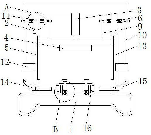
[0006] The purpose of the present invention is to provide a system and a control method for preventing the runaway state in industrial machinery, so as to solve the problem that the system for preventing the runaway state in the industrial machinery in the existing market proposed by the above-mentioned background technology is suppressed. Due to some emergencies, the lower end of the hydraulic rod will fall off. When the worker places the workpiece, it is easy for the hydraulic rod to carry the briquetting block to the worker's arm or palm, which will easily cause damage to the work, and then easily cause a safety accident. In addition, when the system for preventing the out-of-control state in industrial machinery in the traditional market is processing the workpiece, since the processing table is mostly horizontal, when the workpiece is processed, for some relatively light workpieces, the staff is not effective. For some relatively heavy workpieces, when the staff transports them through external transportation devices, such as forklifts, because the workpiece is attached to the processing table, it is not convenient for the staff to pick up the workpiece, thereby reducing the workpiece. The problem of processing efficiency

Method used


Image

  • System for preventing out-of-control state in industrial machine and control method
  • System for preventing out-of-control state in industrial machine and control method
  • System for preventing out-of-control state in industrial machine and control method

Examples


Embodiment Construction

[0032] The following will clearly and completely describe the technical solutions in the embodiments of the present invention with reference to the accompanying drawings in the embodiments of the present invention. Obviously, the described embodiments are only some, not all, embodiments of the present invention. Based on the embodiments of the present invention, all other embodiments obtained by persons of ordinary skill in the art without making creative efforts belong to the protection scope of the present invention.

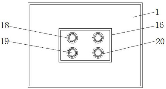
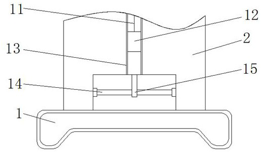
[0033] see Figure 1-6 , the present invention provides a technical solution: a system for preventing an out-of-control state in industrial machinery, including a support base 1, a support rod 2, a hydraulic rod 3, a pressure block 4, a slide groove 5, a support shaft 6, a fixed frame 7, First return spring 8, connecting wire 9, pulling wire 10, rotating groove 11, pressing block 12, limit groove 13, rotating rod 14, protective rod 15, processing table 16, war...


PUM


Abstract

The invention discloses a system for preventing an out-of-control state in an industrial machine and a control method. The system comprises a supporting seat, support shafts, connecting line, traction lines, rotating rods, protection rods and lifting rods, wherein support bars are fixedly welded to the upper surface of the supporting seat; a sliding groove is arranged in the outer surface of each support bar; a rotating groove is arranged in each support bar; a fixing frame is fixedly welded to the outer surface of each support bar; a first reset spring is fixedly welded to the interior of each fixing frame; each connecting wire is fixed to the outer surface of the corresponding support shaft; each traction line is fixedly connected to the outer surface of the corresponding support shaft; and a pressing block is fixedly connected to the lower end of each traction line. According to the system for preventing the out-of-control state in the industrial machine and the control method, in the using process, certain safety of the whole device is still guaranteed in the out-of-control state, and a worker can know whether the whole device leaks electricity or not through flickering of a warning lamp and the alarm sound.

Description

technical field [0001] The invention relates to the technical field of industrial machinery, in particular to a system and a control method for preventing an out-of-control state in industrial machinery. Background technique [0002] In the process of industrial production and life, industrial machinery needs to be used, such as the pressing of workpieces. The pressing of workpieces is to use hydraulic devices to press the workpieces together, so that the workpieces are compressed, the volume changes or the shape of the workpieces changes; [0003] 1. When the system for preventing the out-of-control state in the industrial machinery in the existing market is suppressed, due to some unexpected situations, the lower end of the hydraulic rod will fall off. When the staff places the workpiece, it is easy to make the hydraulic rod carry the briquetting block If it is pressed to the arm or palm of the staff, it is easy to cause damage to the work, and then it is easy to cause saf...

Claims


Application Information

Patent Timeline
Patent Type & Authority Applications(China)
IPC IPC(8): B30B15/32F16P3/06
CPCB30B15/32F16P3/06
Inventor 缪建强
Owner 缪建强
Learn More