Eureka AIR delivers breakthrough ideas for toughest innovation challenges, trusted by R&D personnel around the world.

Anti-overlapping steel bar conveying device

A conveying device and anti-overlapping technology, applied to conveyors, conveyor objects, transportation and packaging, etc., can solve problems such as low production efficiency, hidden safety hazards, and high labor intensity, and achieve safe, reliable, labor-intensive, and high-efficiency effects

Pending Publication Date: 2021-04-30
TJK MACHINERY TIANJIN
View PDF0 Cites 0 Cited by
  • Summary
  • Abstract
  • Description
  • Claims
  • Application Information

AI Technical Summary

Problems solved by technology

[0003] The purpose of the present invention is to provide an anti-overlapping steel bar conveying device to solve the technical problems of high labor intensity, low production efficiency and potential safety hazards that exist in the prior art due to the need to manually level the overlapping steel bars

Method used


Image

  • Anti-overlapping steel bar conveying device
  • Anti-overlapping steel bar conveying device
  • Anti-overlapping steel bar conveying device

Examples


Embodiment Construction

[0036] The technical solutions of the present invention will be further described below in conjunction with the accompanying drawings and embodiments. It should be understood that the specific embodiments described here are only used to explain the present invention, but not to limit the present invention. In addition, it should be noted that, for the convenience of description, only the parts related to the present invention are shown in the drawings but not all of them.

[0037] In the description of the present invention, unless otherwise clearly specified and limited, the terms "connected", "connected" and "fixed" should be understood in a broad sense, for example, it can be a fixed connection, a detachable connection, or an integrated ; It can be a mechanical connection or an electrical connection; it can be a direct connection or an indirect connection through an intermediary, and it can be the internal communication of two components or the interaction relationship betw...


PUM


Abstract

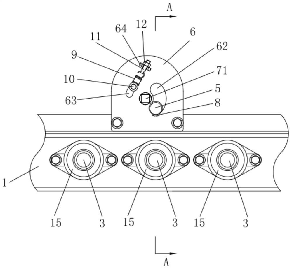
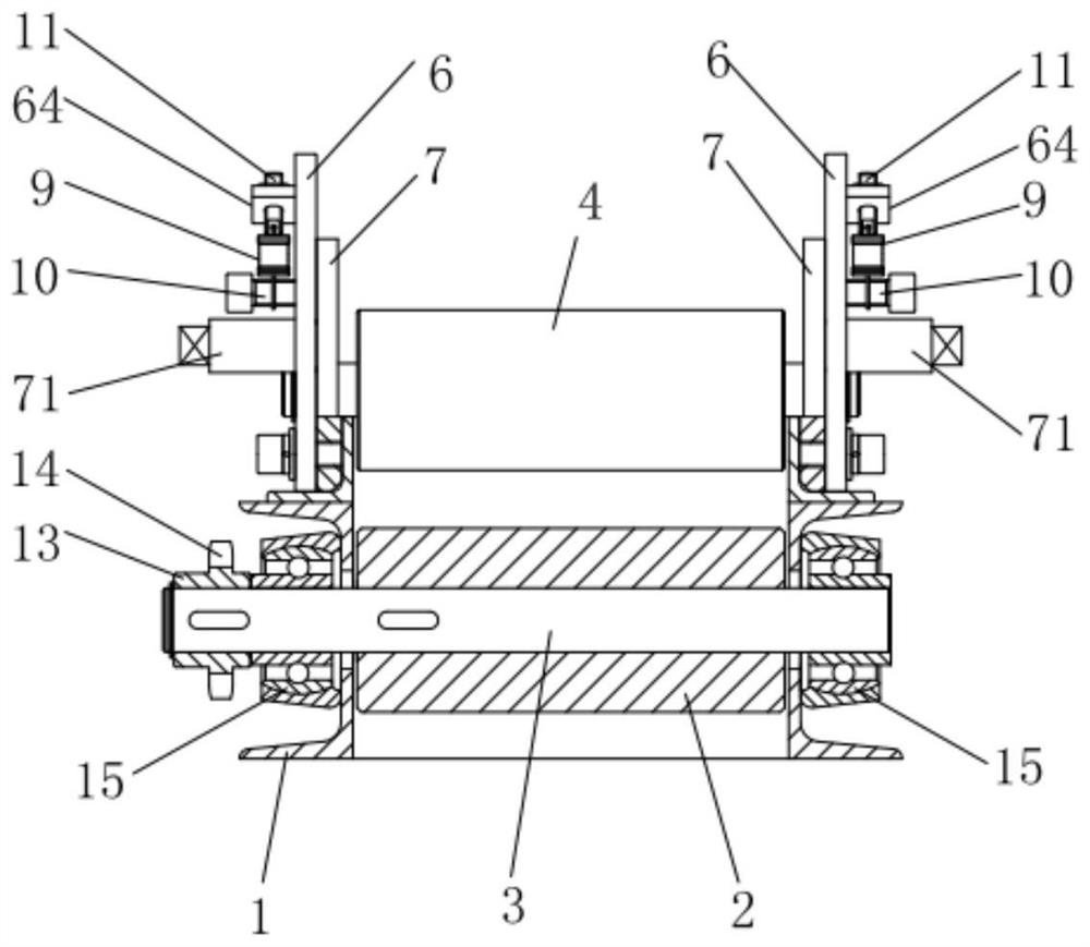
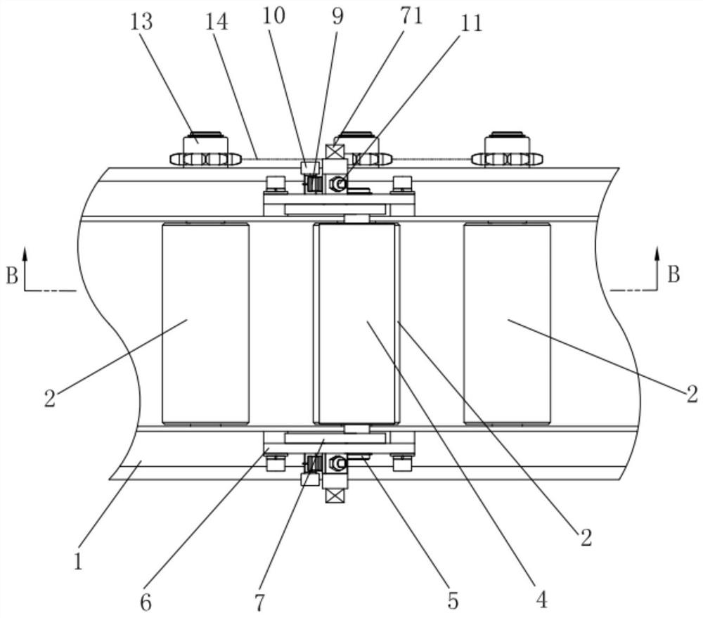
The invention relates to the technical field of steel bar machining production lines, and particularly relates to an anti-overlapping steel bar conveying device. The anti-overlapping steel bar conveying device comprises a conveying frame, conveying rollers and a pressing roller, wherein the conveying rollers are pivoted to the conveying frame through conveying roller shafts, and a plurality of conveying rollers are arranged on the conveying frame in the first direction at intervals; the pressing roller is located above the conveying rollers, the axis of the pressing roller is parallel to the axes of the conveying rollers, the pressing roller is arranged between a first position and a second position in a floating manner, the second position is higher than the first position, and the diameter of a steel bar is set to be D; and when the pressing roller is located at the first position and the second position, the distance between the pressing roller and each conveying roller is larger than or equal to D and smaller than 2D. According to the anti-overlapping steel bar conveying device, the pressing roller can apply downward pressure to the steel bar located on the upper layer in the floating process, and therefore the steel bar located on the upper layer is pressed downwards to be flush with the steel bar located on the lower layer, automatic arrangement of the overlapped steel bars is achieved, and the beneficial effects of being high in efficiency, safe, reliable and low in labor intensity are achieved.

Description

technical field [0001] The invention relates to the technical field of steel bar processing production lines, in particular to an anti-overlapping steel bar conveying device. Background technique [0002] In the steel bar processing production line, the steel bar conveying device is usually used to transport the steel bars. During the process of steel bar transport, there will be overlapping steel bars. In the existing technology, it is necessary to manually arrange the overlapping steel bars to facilitate the next process. . The prior art has the defects of high labor intensity, low production efficiency and potential safety hazards. Contents of the invention [0003] The purpose of the present invention is to provide an anti-overlapping steel bar conveying device to solve the technical problems of high labor intensity, low production efficiency and potential safety hazards that exist in the prior art due to the need to manually level the overlapping steel bars . [00...

Claims


Application Information

Patent Timeline
Patent Type & Authority Applications(China)
IPC IPC(8): B65G13/00B65G47/22
CPCB65G13/00B65G47/22B65G2201/0217
Inventor 陈振东其他发明人请求不公开姓名
Owner TJK MACHINERY TIANJIN
Why Eureka
Eureka Blog
Learn More