Engine intake pipe and its processing and positioning tooling

A technology for intake pipes and positioning tooling, which is applied to positioning devices, engine components, machines/engines, etc. It can solve problems such as uneven installation end faces, poor position accuracy, and complex positioning mechanisms, so as to save installation space and reduce processing difficulty Effect

Active Publication Date: 2022-05-10
宁波裕隆汽车制泵有限公司
View PDF0 Cites 0 Cited by
  • Summary
  • Abstract
  • Description
  • Claims
  • Application Information

AI Technical Summary

Problems solved by technology

[0003] The design of the existing intake manifold is relatively simple, and usually only one air inlet and one air outlet are provided. However, with the application of the exhaust gas recirculation system (abbreviated as the EGR system) in the engine, the existing intake manifold has no The EGR intake pipe cannot prevent EGR exhaust gas from mixing with fresh air, which requires adding EGR intake pipes and pipes connecting EGR and intake pipes in other parts, resulting in poor layout of the intake system. compact
In addition, in the prior art, the positioning mechanism for the machining of the intake pipe is relatively complicated, or the positioning of the workpiece is not stable enough, and the position degree is poor, resulting in unevenness of the installation end surface during the installation of the machined intake pipe structure. Case

Method used


Image

  • Engine intake pipe and its processing and positioning tooling
  • Engine intake pipe and its processing and positioning tooling
  • Engine intake pipe and its processing and positioning tooling

Examples


Embodiment Construction

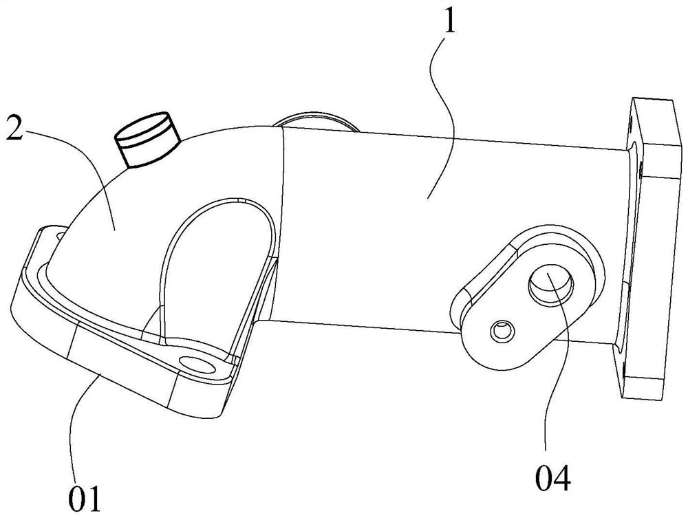
[0029] The present invention will be further described below in conjunction with the accompanying drawings and specific embodiments.

[0030] In the description of the present invention, it should be noted that the terms "inner cavity", "side wall", "central position", "inner end surface", "outer end surface", "upper end", "lower end", "middle part", The orientation or positional relationship indicated by "top surface" is based on the orientation or positional relationship shown in the drawings, and is only for the convenience of describing the present invention and simplifying the description, rather than indicating or implying that the referred device or element must have a specific orientation , constructed and operated in a particular orientation and therefore should not be construed as limiting the invention. In addition, it should be noted that the terms "first" and "second" are only used for descriptive purposes, and should not be understood as indicating or implying re...


PUM


Abstract

The invention discloses an engine air intake connecting pipe, which comprises a vertical pipe and an arc pipe, one end of the arc pipe is provided with an air inlet, one end of the vertical pipe is provided with an air outlet, and the side wall of the other end is provided with an EGR system air intake port and EGR valve installation port; the inner cavity of the vertical pipe near the gas outlet is detachably provided with a mixing pipe; the mixing pipe includes an outer connecting pipe and an inner connecting rod, and the inner connecting rod is passed through the center of the outer connecting pipe , and the inner connecting rod and the outer connecting pipe are connected and fixed by several helical blades, and the several helical blades are helically arranged along the same direction. The invention also discloses a processing and positioning tool specially used for the machining and clamping of the engine intake connection pipe. The engine air intake pipe and its processing and positioning tool provided by the present invention realize the mixed reuse of exhaust gas intake and fresh air, the pipeline structure is simple, and the space occupied is small; and it is fixed by a special clamping tool, and the positioning is stable. precise.

Description

technical field [0001] The invention relates to the technical field of automobile engines, in particular to an engine intake connection pipe and a processing and positioning tool thereof. Background technique [0002] With the increasingly stringent emission and fuel consumption regulations, the intake manifold of the engine is an important part of organizing intake air, and its design also needs to be continuously updated. [0003] The design of the existing intake manifold is relatively simple, and usually only one air inlet and one air outlet are provided. However, with the application of the exhaust gas recirculation system (abbreviated as the EGR system) in the engine, the existing intake manifold has no The EGR intake pipe cannot prevent EGR exhaust gas from mixing with fresh air, which requires adding EGR intake pipes and pipes connecting EGR and intake pipes in other parts, resulting in poor layout of the intake system. compact. In addition, in the prior art, the p...

Claims


Application Information

Patent Timeline
Patent Type & Authority Patents(China)
IPC IPC(8): F02M35/10F02M26/21B23Q3/08
CPCF02M35/10F02M35/10091F02M35/10222F02M35/10255F02M35/10367F02M26/21B23Q3/062B23Q3/08B23Q2703/04
Inventor 胡松海李志军
Owner 宁波裕隆汽车制泵有限公司
Why Eureka
Try Eureka