
Hydrodynamic retarder rotor

A hydraulic retarder and rotor technology, applied in the direction of liquid resistance brakes, brake types, mechanical equipment, etc., can solve the problems of high cost, poor effect, complex structure, etc.

Active Publication Date: 2021-04-30
FAW JIEFANG AUTOMOTIVE CO
View PDF28 Cites 2 Cited by
  • Summary
  • Abstract
  • Description
  • Claims
  • Application Information

AI Technical Summary

Problems solved by technology

[0003] At present, the brake torque is adjusted by adjusting the liquid filling amount (the ratio of oil and air content inside the hydraulic retarder). The size of the torque, one is electric drive to control the opening of the oil inlet channel to adjust the braking torque, so as to achieve the purpose of adjusting the braking torque of the hydraulic retarder according to the road conditions. Load loss, but the effect is not good, usually need to add additional loss reduction device, making the structure complex and high cost

Method used


Image

  • Hydrodynamic retarder rotor
  • Hydrodynamic retarder rotor
  • Hydrodynamic retarder rotor

Examples


Embodiment Construction

[0033] Embodiments of the present invention will be described in detail below, and examples of the embodiments are shown in the drawings, wherein the same or similar reference numerals denote the same or similar components or components having the same or similar functions throughout. The embodiments described below by referring to the figures are exemplary and are intended to explain the present invention and should not be construed as limiting the present invention.

[0034] In the description of the present invention, unless otherwise clearly stipulated and limited, the terms "connected", "connected" and "installed" should be understood in a broad sense, for example, it can be an installation connection, a detachable connection, or a mechanical connection. A connection can also be an electrical connection, a direct connection, or an indirect connection through an intermediary, or an internal connection between two elements or an interaction relationship between two elements....


PUM


Abstract

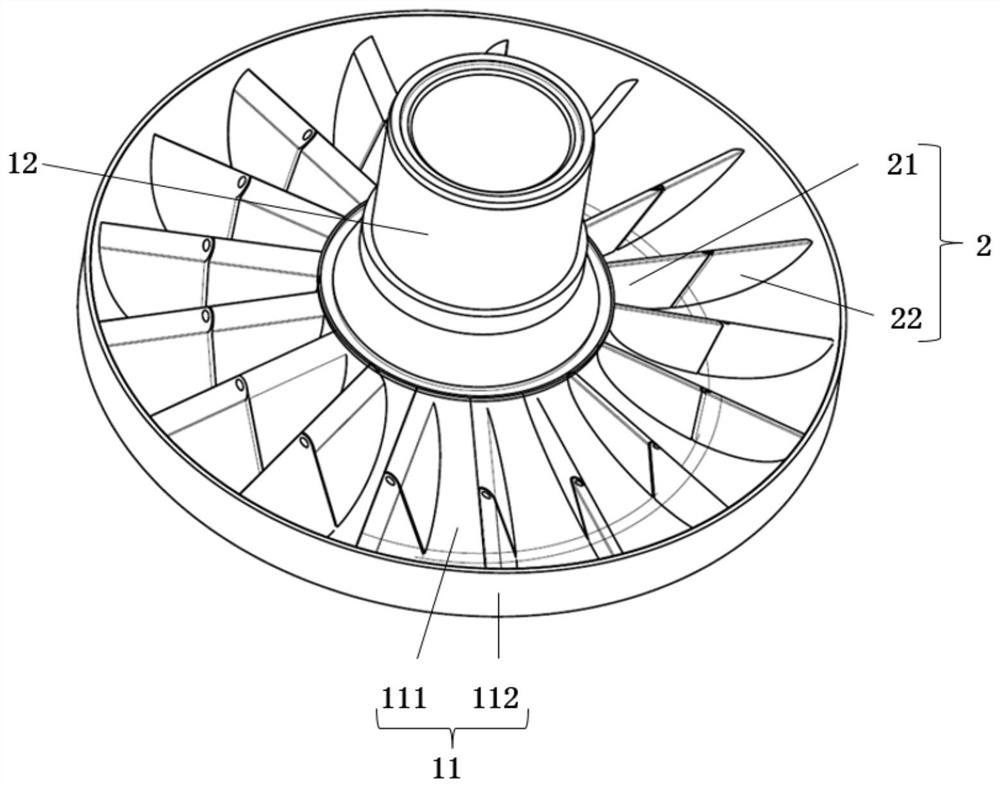
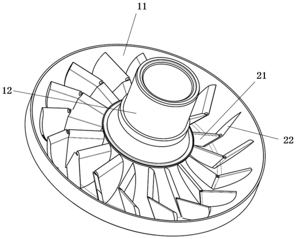
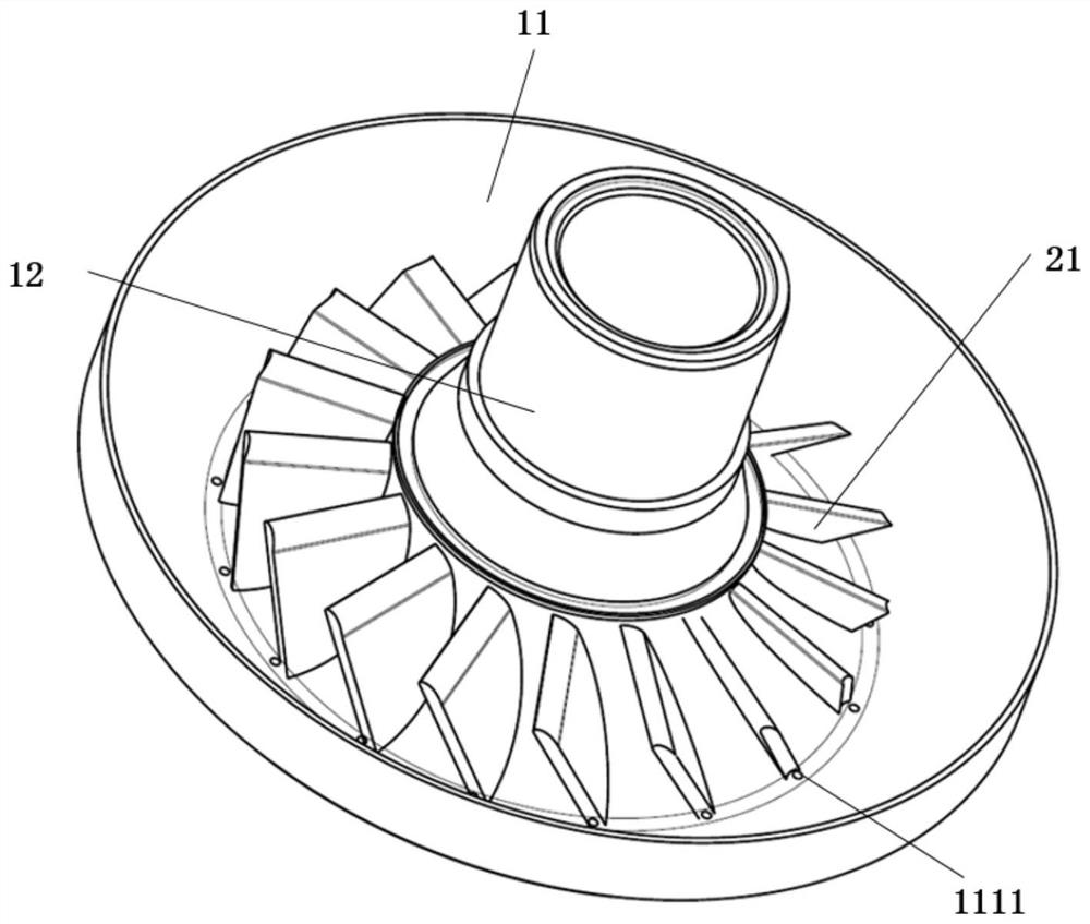
The invention belongs to the technical field of retarders, and discloses a hydrodynamic retarder rotor. The hydrodynamic retarder rotor comprises a rotor disc and a plurality of blades, and the rotor disc comprises a disc body and a middle shaft connected to the disc body; the blades are evenly distributed around the circumference of the middle shaft, each blade comprises a fixed piece part and a rotating piece part, the fixed piece parts are fixedly connected to the disc body and extend in the radial direction of the disc body, the rotating piece parts are rotationally arranged on the disc body, the blades have a working state and a loss reduction state, in the working state, the rotating piece parts and the fixed piece parts abut against each other and are coplanar, and in the loss reduction state, an included angle is formed between each rotating piece part and the corresponding fixed piece part. In the working state, the fixed piece parts and the rotating piece parts form the unfolded blades, at the moment, the acting area of pressure oil on the blades reaches the maximum, and large braking torque is generated on the blades; and when no-load occurs, the blades are adjusted to be in the loss reduction state, the included angle is formed between each rotating piece part and the corresponding fixed piece part, the bent blades are formed, the acting area of pressure oil on the blades is reduced, and therefore the effect of reducing no-load losses is achieved.

Description

technical field [0001] The invention belongs to the technical field of retarders, in particular to a hydraulic retarder rotor. Background technique [0002] The hydraulic retarder is a device that uses liquid damping to produce a retarding effect. Its main working principle is that the rotation of the rotor drives the rotation of the pressure oil, thereby acting a torque on the stator, and the counter torque of the stator becomes the braking torque of the rotor. [0003] At present, the brake torque is adjusted by adjusting the liquid filling amount (the ratio of oil and air content inside the hydraulic retarder). The size of the torque, one is electric drive to control the opening of the oil inlet channel to adjust the braking torque, so as to achieve the purpose of adjusting the braking torque of the hydraulic retarder according to the road conditions. Load loss, but the effect is not good, usually need to add additional loss reduction device, making the structure comple...

Claims


Application Information

Patent Timeline
IPC IPC(8): F16D57/02F16D57/00
CPCF16D57/02F16D57/005F16D57/007Y02T10/64
Inventor 张樱玮孙国晖徐国林王丽娜王琪韩旭李振国惠帅平
Owner FAW JIEFANG AUTOMOTIVE CO
Learn More