Air conditioner and air outlet structure for air conditioner

A technology for air outlets and air conditioners, which is applied in air conditioning systems, space heating and ventilation, space heating and ventilation details, etc. It can solve problems such as the unsatisfactory air guide effect of the air outlet structure, and achieve reduced air leakage and beautiful appearance And simplicity, enhance the effect of wind guide effect

Pending Publication Date: 2021-04-30
QINGDAO HAIER AIR CONDITIONING ELECTRONICS CO LTD +2
View PDF0 Cites 1 Cited by
  • Summary
  • Abstract
  • Description
  • Claims
  • Application Information

AI Technical Summary

Problems solved by technology

[0005] In order to solve the above-mentioned problems in the prior art, that is, to solve the problem that the air guide effect of the air outlet structure of the existing air conditioner is not ideal, the present invention provides an air outlet structure for the air conditioner, the air outlet structure includes an air outlet A wind frame, an air guide assembly and a push-pull assembly, the air outlet frame is provided with an air outlet; wherein, the air guide assembly includes at least one air guide panel, and the at least one air guide panel can cover the The air outlet, and the total area of ​​the at least one air guide panel is greater than or equal to the area of ​​the surface where the air outlet is located; the push-pull assembly is arranged on the air outlet frame, and the push-pull assembly and the at least one air guide Panel connection, used to drive the at least one air guide panel to expand and contract relative to the air outlet, so as to realize the opening or closing of the air outlet

Method used


Image

  • Air conditioner and air outlet structure for air conditioner
  • Air conditioner and air outlet structure for air conditioner
  • Air conditioner and air outlet structure for air conditioner

Examples


Embodiment Construction

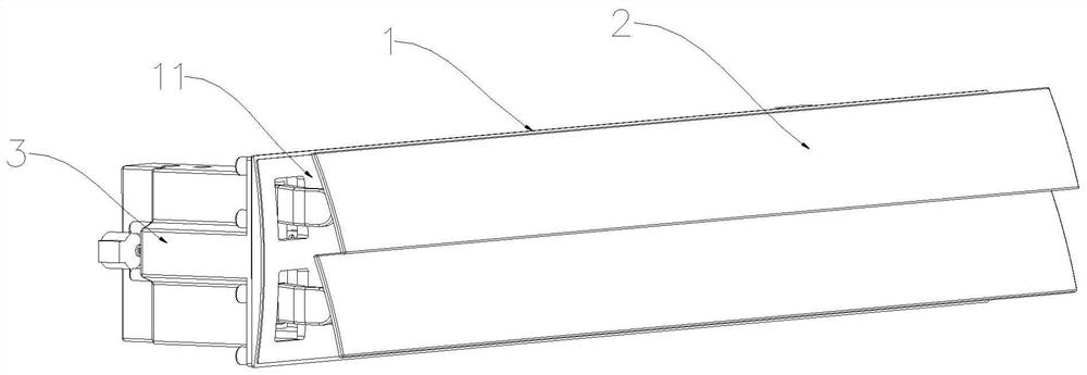
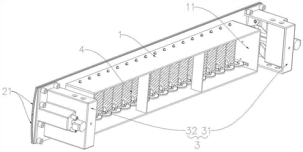
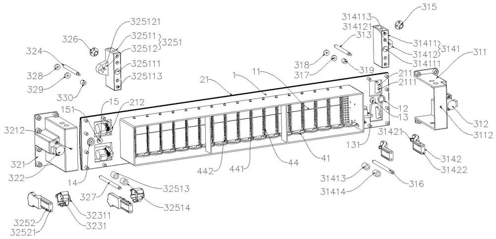
[0046] Preferred embodiments of the present invention are described below with reference to the accompanying drawings. Those skilled in the art should understand that these embodiments are only used to explain the technical principles of the present invention, and are not intended to limit the protection scope of the present invention. For example, although the first drive mechanism and the second drive mechanism in the accompanying drawings are respectively arranged on the left and right sides of the air outlet frame, this arrangement is not static, and those skilled in the art can make adjustments to it as needed to adapt to specific conditions. application occasions. For example, the first drive mechanism and the second drive mechanism can be arranged on the upper and lower sides or the same side of the air outlet frame.

[0047] It should be noted that, in the description of the present invention, terms such as "inner", "outer", "upper", "lower", "left", "right" and other...


PUM


Abstract

The invention relates to the technical field of intelligent electric appliances, in particular to an air conditioner and an air outlet structure for the air conditioner. The air conditioner and the air outlet structure for the air conditioner aim at solving the problem that an existing air outlet structure of an air conditioner is not ideal in air guiding effect. In order to achieve the purpose, the air outlet structure for the air conditioner comprises an air outlet frame, an air guiding assembly and a push-pull assembly, and an air outlet is formed in the air outlet frame; the air guiding assembly comprises at least one air guiding panel, the air guiding panels can cover the air outlet when in a closed state, and the total area of the air guiding panels is larger than or equal to the area of the face where the air outlet is located; and the push-pull assembly is arranged on the air outlet frame, connected with the air guiding panels and used for driving the air guiding panels to stretch and retract relative to the air outlet, and therefore opening or closing of the air outlet is achieved, the total area of the air guiding assembly is increased, the air guiding effect is improved, the appearance of an air duct machine is more attractive and simpler, and the visual effect of a user is improved.

Description

technical field [0001] The invention relates to the technical field of smart appliances, in particular to an air outlet structure for an air conditioner and the air conditioner. Background technique [0002] As air conditioners are widely used in thousands of households, users have higher and higher requirements for the performance of air conditioners. Taking the air duct machine as an example, the air outlet of the volute in the air duct machine is directly opposite to the air outlet of the air duct machine, so that the blowing direction of the air duct machine is single, and it can only blow straight ahead, and the air can not be upward or downward. , unable to effectively adjust the air outlet direction. [0003] In order to solve the above problems, in the prior art, the air duct machine is provided with an air outlet structure for guiding the air. The air outlet structure includes an air outlet frame, a decorative panel and an air guide plate. The decorative panel is l...

Claims


Application Information

Patent Timeline
Patent Type & Authority Applications(China)
IPC IPC(8): F24F1/0011F24F13/14
CPCF24F1/0011F24F13/1413F24F13/1426F24F2013/1433
Inventor 蔡艳芳张中晓
Owner QINGDAO HAIER AIR CONDITIONING ELECTRONICS CO LTD
Why Eureka
Try Eureka