Eureka AIR delivers breakthrough ideas for toughest innovation challenges, trusted by R&D personnel around the world.

External particle heat absorber and solar power generation system

An external heat absorber technology, applied in solar thermal power generation, solar heating systems, solar thermal energy, etc., can solve the problem of low heat absorption efficiency of particle heat absorbers

Active Publication Date: 2021-04-30
浙江高晟光热发电技术研究院有限公司
View PDF5 Cites 3 Cited by
  • Summary
  • Abstract
  • Description
  • Claims
  • Application Information

AI Technical Summary

Problems solved by technology

[0008] The technical problem to be solved by the present invention is to provide an external particle heat absorber and solar power generation system to solve the problem of low heat absorption efficiency of the existing particle heat absorber

Method used

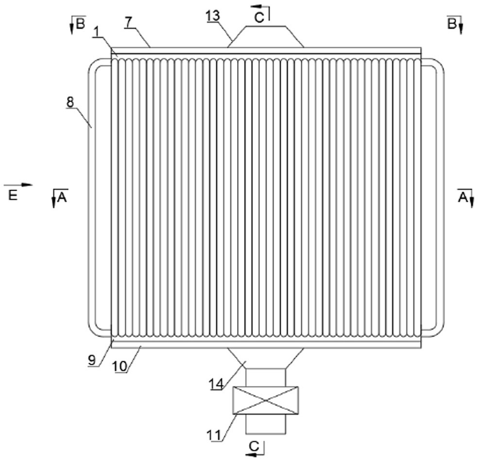
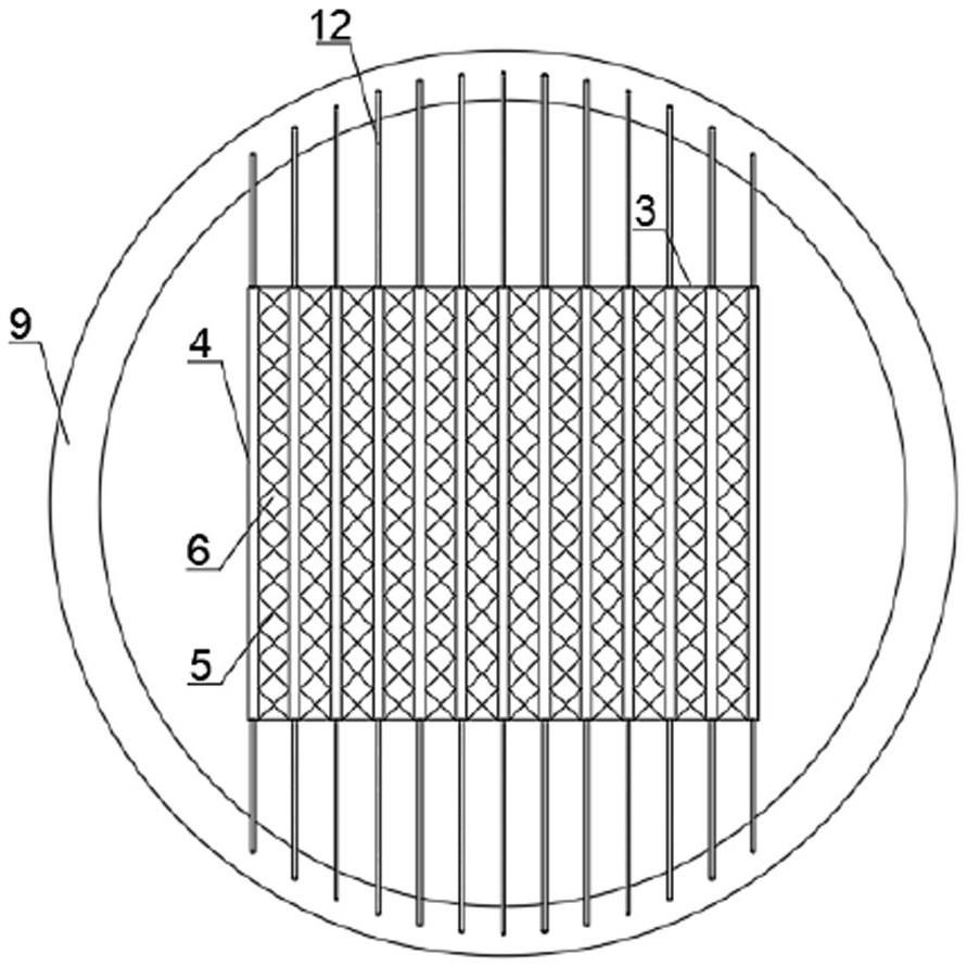
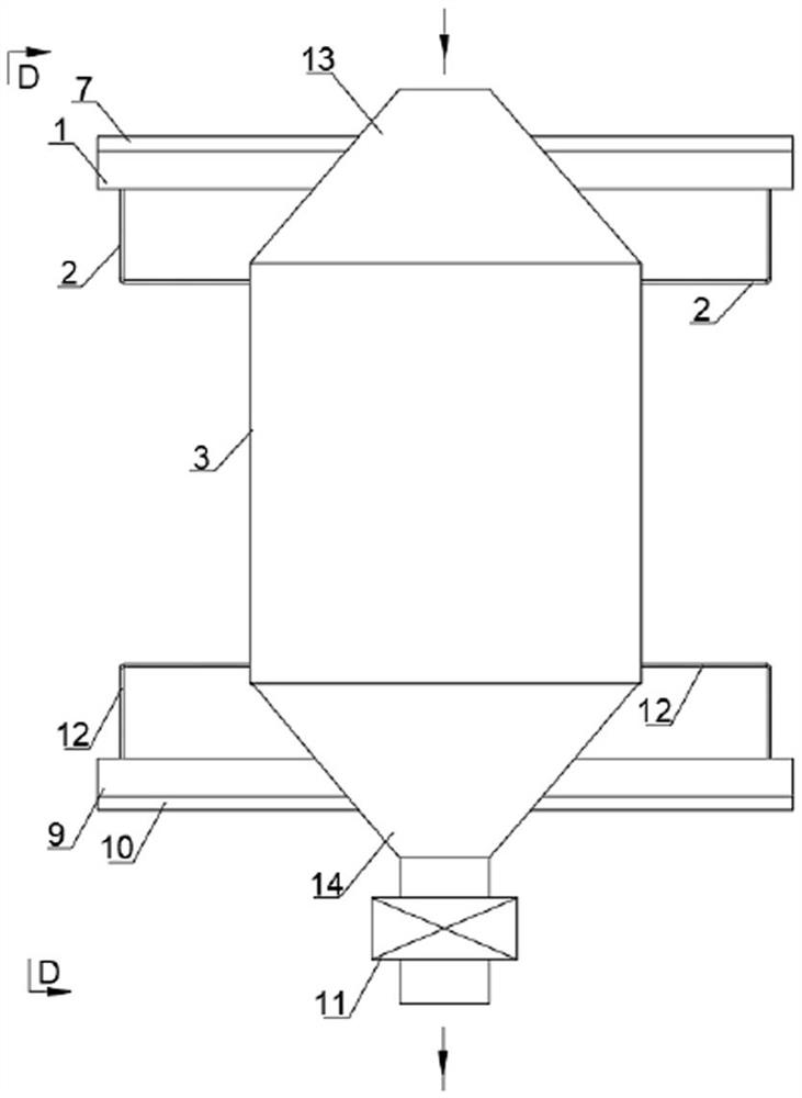

Image

  • External particle heat absorber and solar power generation system
  • External particle heat absorber and solar power generation system
  • External particle heat absorber and solar power generation system

Examples


Embodiment 1

[0046] see Figure 1 to Figure 6, In one embodiment, an external particle heat absorber includes a particle heat exchanger 3 and a heat absorption tube group 8 for receiving solar energy. The particle heat exchanger 3 is provided with at least one particle channel 6 and at least one working medium channel 4, and the working medium channel 4 is in heat transfer contact with the particle channel 6, so that the particles in each particle channel 6 can be connected to the working medium channel The phase change working medium in 4 performs heat exchange. The heat-absorbing tube group 8 is filled with a phase-change working fluid whose evaporation temperature is higher than the heat-absorbing temperature of the particles circulating in the particle channel 6 . The output end of the heat-absorbing tube group 8 is connected with the input end of the working medium channel 4, and the input end of the heat-absorbing tube group 8 is connected with the output end of the working medium c...

Embodiment 2

[0072] A solar power generation system, comprising the external particle heat absorber in the first embodiment above. By setting the phase change working medium as the intermediate heat exchange medium, the heat is transferred to the particles after evaporation and the particles are raised to the required temperature, which has higher efficiency. At the same time, the external heat sink structure is adopted, which is conducive to the expansion of the installed capacity of the power station, thereby reducing the investment cost per unit scale. The external heat sink can be arranged in a circular mirror field to increase land utilization.


PUM


Abstract

The invention discloses an external particle heat absorber and a solar power generation system. A particle heat exchanger internally provided with a particle channel and a working medium channel is arranged, meanwhile, a heat absorption pipe group is arranged to be communicated with two ends of the working medium channel to form a circulating pipeline, the working medium channel is in heat transfer contact with the particle channel, and after a phase change working medium in the heat absorption pipe group absorbs heat and is evaporated into a gaseous phase change working medium, the gaseous phase change working medium enters the working medium channel to exchange heat with the cold particles in the particle channel and is condensed into a liquid phase change working medium which flows back to the heat absorption pipe group. The heated hot particles can be output to next external equipment from the output end of the particle channel. The liquid phase change working medium is arranged as the middle heat exchange medium, heat is transmitted to the particles after evaporation, and the particles are heated to the needed temperature, so that high efficiency is achieved, and the problem that an existing particle heat absorber is low in heat absorption efficiency is solved. Meanwhile, the particle technology is low in price and higher in heat absorption temperature, and the kilowatt-hour cost of a photo-thermal power station can be greatly reduced under the condition of the same heat absorption efficiency.

Description

technical field [0001] The invention belongs to the technical field of solar thermal power generation, and in particular relates to an external particle heat absorber and a solar power generation system. Background technique [0002] Solar energy is a green, sustainable and clean energy, so it may become an ideal main energy source in the future. Solar thermal power generation is equipped with large-scale and cheap energy storage technology, so the power output is smooth, stable and dispatchable, and has broad application prospects. [0003] Solid particle heat absorption and storage technology is a new type of solar heat absorption and storage technology, and it is one of the mainstream technologies in the research of third-generation tower-type photothermal power generation. Its main advantages are as follows: solid particles can simultaneously meet the requirements of heat absorption, heat transfer and heat storage. Demand; the cost of particles is low; the heat absorpti...

Claims


Application Information

Patent Timeline
Patent Type & Authority Applications(China)
IPC IPC(8): F24S10/30F24S10/95F24S70/60F24S80/20F03G6/06
CPCF03G6/06F24S10/30F24S10/95F24S70/60F24S80/20F24S2070/62Y02E10/44Y02E10/46
Inventor 俞明锋章晓敏宓霄凌
Owner 浙江高晟光热发电技术研究院有限公司
Why Eureka
Eureka Blog
Learn More