
Refrigeration equipment capable of automatically dissipating heat

A refrigeration equipment and automatic technology, applied in lighting and heating equipment, household refrigeration devices, household appliances, etc., can solve problems such as affecting heat dissipation effect, low service life, affecting stability, etc., to improve stability and service life, The effect of improving the service life

Inactive Publication Date: 2021-04-30
吴小香
View PDF0 Cites 1 Cited by
  • Summary
  • Abstract
  • Description
  • Claims
  • Application Information

AI Technical Summary

Problems solved by technology

[0003] Existing refrigerating devices emit a large amount of heat during use. Existing refrigerating equipment is generally blown by a fan, and the heat in the box is discharged through cooling holes, thereby performing air cooling and heat dissipation. It is easy to block the heat dissipation holes, causing the heat to be unable to be discharged, affecting the heat dissipation effect, and even dust entering the main body, which may cause a short circuit inside the main body and affect the service life of the main body. Therefore, some refrigeration devices that sense the temperature through the temperature sensing device to drive the operation of the heat dissipation mechanism have also appeared on the market, and the temperature sensing mechanism of this kind of device is generally measured by a temperature sensor. Using this kind of electronic components, the service life is not high, affecting stability

Method used


Image

  • Refrigeration equipment capable of automatically dissipating heat
  • Refrigeration equipment capable of automatically dissipating heat
  • Refrigeration equipment capable of automatically dissipating heat

Examples


Embodiment Construction

[0025] The present invention is described in further detail now in conjunction with accompanying drawing. These drawings are all simplified schematic diagrams, which only illustrate the basic structure of the present invention in a schematic manner, so they only show the configurations related to the present invention.

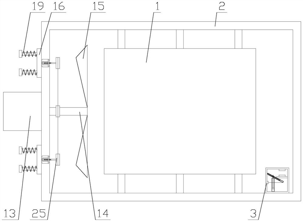
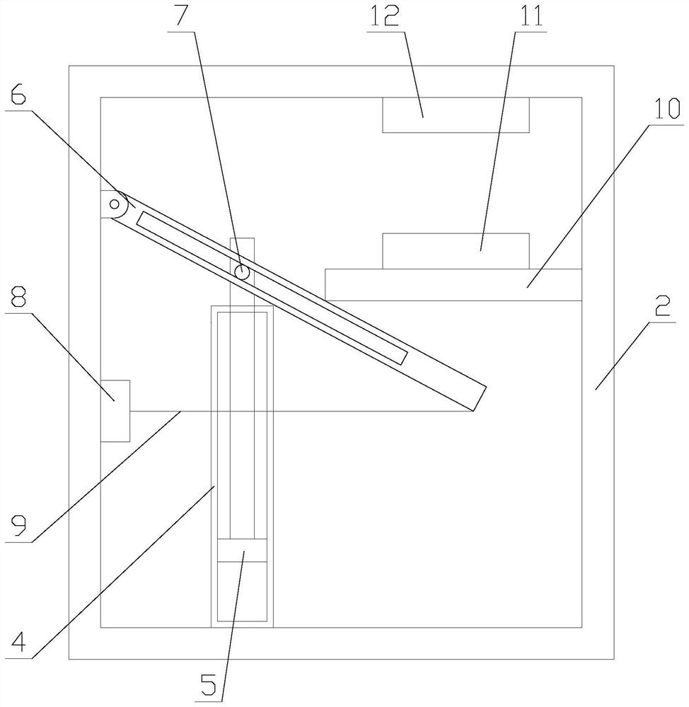
[0026] Such as figure 1 As shown, a refrigeration device capable of automatically dissipating heat includes a main body 1, a box body 2, a heat dissipation mechanism and a trigger mechanism. The main body 1 is arranged in the box body 2, and the heat dissipation mechanism is arranged on one side of the box body 2. The trigger mechanism is arranged in the box body 2;

[0027] When the device is in use, the main body 1 is operated, the main body 1 dissipates heat, the heat on the main body 1 is absorbed through the box body 2, and then heat exchange is performed with the air, thereby realizing heat dissipation. Here, the box body 2 increases the contact area wi...


PUM


Abstract

The invention relates to refrigeration equipment capable of automatically dissipating heat. The refrigeration equipment comprises a main body, a heat dissipation mechanism and a trigger mechanism. According to the refrigeration equipment, the temperature in a box is sensed via the trigger mechanism, power is supplied to the heat dissipation mechanism, and heat of the main body is dissipated through the heat dissipation mechanism. Compared with an existing trigger mechanism, the trigger mechanism avoids use of electronic elements such as a temperature sensor through a pure mechanical structure, the stability of the device is improved, the service life of the device is prolonged, a motor stops supplying power only when the temperature is reduced to a certain degree, sudden running or stopping of the motor due to unstable connection of a first electric sheet and a second electric sheet when the temperature floats is avoided, and the service life of the motor is prolonged. Compared with an existing heat dissipation mechanism, through linkage of an air cooling assembly and a sealing assembly, it is guaranteed that heat can be stably discharged through heat dissipation holes, meanwhile, when the air cooling assembly stops running, the heat dissipation holes are kept in a sealed state, dust is prevented from blocking the heat dissipation holes, and the service life of the main body is prolonged.

Description

technical field [0001] The invention relates to a refrigeration device capable of automatically dissipating heat. Background technique [0002] Refrigeration equipment refers to equipment mainly used for food refrigeration, various cargo refrigeration and cabin air conditioning in summer. It is mainly composed of compressors, expansion valves, evaporators, condensers and accessories, and pipelines. According to the working principle, it can be divided into Compression refrigeration equipment, absorption refrigeration equipment, steam injection refrigeration equipment, heat pump refrigeration equipment and electric refrigeration equipment, etc., remove the heat from the object and its surroundings through the working cycle of the equipment, causing and maintaining a certain low temperature state. [0003] Existing refrigerating devices emit a large amount of heat during use. Existing refrigerating equipment is generally blown by a fan, and the heat in the box is discharged th...

Claims


Application Information

Patent Timeline
IPC IPC(8): F25D23/00F25D29/00
CPCF25D23/003F25D29/005
Inventor 吴小香
Owner 吴小香
Learn More