

Special motor for paper shredder
A paper shredder and motor technology, which is applied in electromechanical devices, casings/covers/supports, cooling/ventilation devices, etc., can solve problems such as unsatisfactory heat dissipation and complex structures, and achieve structure reduction, volume reduction, and convenience. The effect of heat dissipation
- Summary
- Abstract
- Description
- Claims
- Application Information
AI Technical Summary
Problems solved by technology
Method used
Image

Examples
Embodiment 1
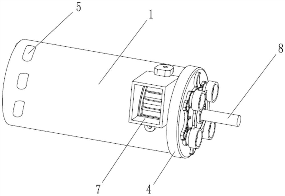
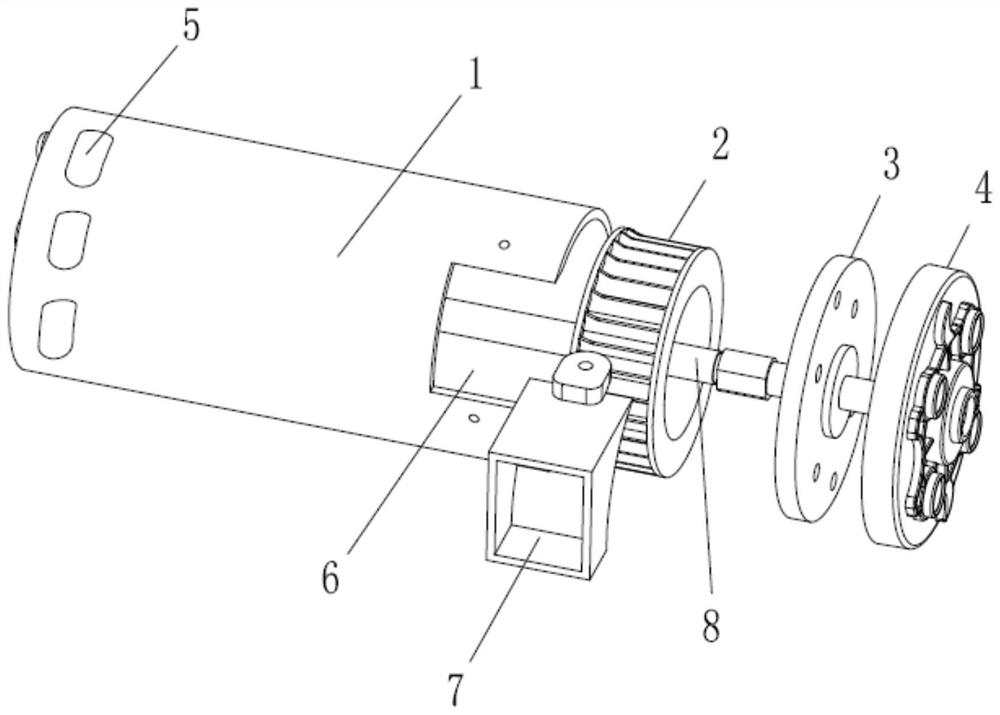
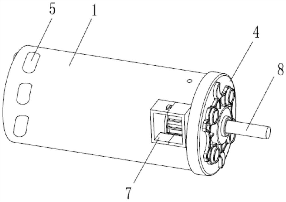
[0022] Example 1: from figure 1 and figure 2 You can clearly see the special motor for shredders, including: motor 1, fan 2 installed at the output end of motor 1, end cover 3 and insulating sheet 4.
[0023] The non-output end of the motor 1 is provided with an air inlet 5, the output end of the motor 1 is provided with a fan installation chamber 6, and the fan installation chamber 6 is provided with an air outlet 7, and the air inlet 5 and the air outlet 7 arranged at both ends of the motor 1 are connected. .
[0024] The fan 2 is installed on the output shaft 8 of the motor in the fan installation cavity 6 , the fan installation cavity 6 is closed by the end cover 3 , and the output shaft 8 of the motor 1 protrudes from the center hole of the end cover 3 .
[0025] The insulating sheet 4 is inserted on the output shaft 8 of the motor outside the end cover 3 .
Embodiment 2
[0026] Example 2: From image 3 and Figure 4 It can be seen that the basic structure of the special motor for shredders of the present invention is the same as that of Embodiment 1, the only difference being:
[0027] The fan 2 is installed in a fan box 9 made of a cavity box 91 and a cavity cover 92. The fan box 9 is provided with an air outlet 7, and the center of the cavity box 91 is provided with a suction port 5 communicating with the non-output end air inlet 5 of the motor 1. The hole 93 and the chamber cover 92 are provided with a central hole for the output shaft 8 of the motor 1 to pass through. The fan 2 is installed on the output shaft 8 of the motor 1 in the fan box 9, and the fan box 9 is fixed and installed in the fan installation cavity 6 by screws.
PUM
 Abstract
Description
Claims
Application Information