
A Class J Power Amplifier

A technology for power amplifiers and power amplification, which is applied in the direction of power amplifiers, etc., and can solve the problems of low power output capability and power gain capability, limiting the limit efficiency of class J power amplifiers, etc.

Active Publication Date: 2021-06-18
CHENGDU UNIVERSITY OF TECHNOLOGY
View PDF7 Cites 0 Cited by
  • Summary
  • Abstract
  • Description
  • Claims
  • Application Information

AI Technical Summary

Problems solved by technology

However, in order to form the special voltage half-sine waveform of the class J amplifier, the fundamental frequency output impedance of the output matching circuit can only be a complex impedance or a negative impedance. Since the negative impedance cannot be realized in practice, only a relatively limited pure reactance can be used. The complex impedance form, but this limits the ultimate efficiency of the traditional class J power amplifier
[0004] In addition, the existing high-efficiency FET power amplifiers are often implemented based on a single common-source transistor, which is limited by a single transistor, and the power output capability and power gain capability are relatively low

Method used


Image

  • A Class J Power Amplifier
  • A Class J Power Amplifier
  • A Class J Power Amplifier

Examples


Embodiment Construction

[0020] Exemplary embodiments of the present invention will now be described in detail with reference to the accompanying drawings. It should be understood that the implementations shown and described in the drawings are only exemplary, intended to explain the principle and spirit of the present invention, rather than limit the scope of the present invention.

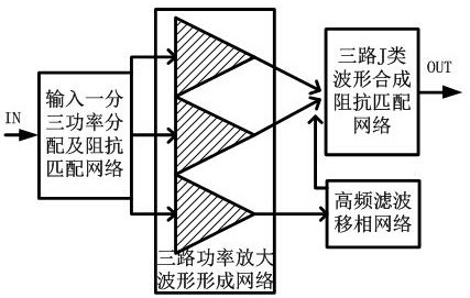
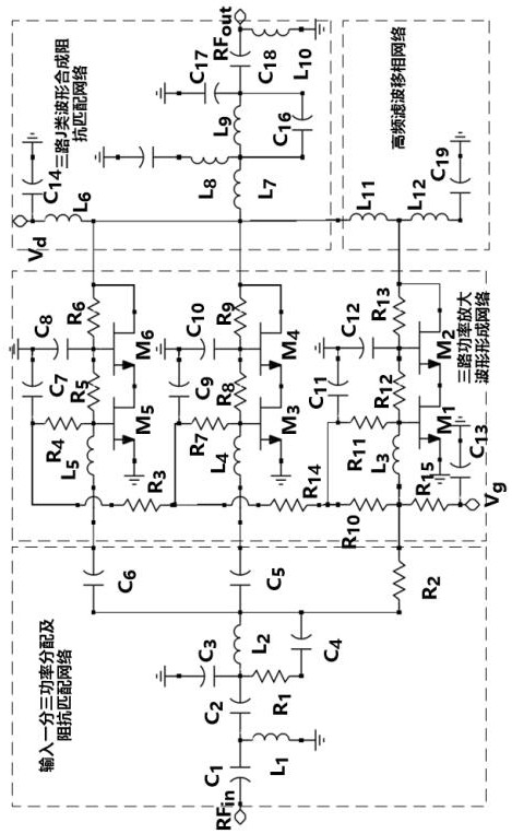
[0021] An embodiment of the present invention provides a class J power amplifier, such as figure 1 As shown, it includes input one-to-three power distribution and impedance matching network, three-way power amplification waveform forming network, high-frequency filter phase-shifting network, three-way J-type waveform synthesis impedance matching network; input one-to-three power distribution and impedance matching network The input end of the high-efficiency class J power amplifier is the input end, and the output end of the three-way class J waveform synthesis impedance matching network is the output end of the entire h...


PUM


Abstract

The invention discloses a class J power amplifier, which comprises an input-one-to-three power distribution and impedance matching network, a three-way power amplification waveform forming network, a high-frequency filtering phase-shifting network, and a three-way J-type waveform synthesis impedance matching network. The invention adopts the power amplification structure based on the three-way self-bias mode to form a waveform forming network, combines the three-way J-type waveform synthesis technology and the J-type amplifier impedance matching technology, and directly shapes the output voltage waveform of the amplifier into a special voltage half of the J-type amplifier. The sinusoidal waveform avoids the negative impedance limitation of the output network, improves the limit efficiency of the traditional class J amplifier, and makes the circuit have the characteristics of ultra-wideband, high gain, and high power output capability.

Description

technical field [0001] The invention belongs to the technical field of field effect transistor radio frequency power amplifiers and integrated circuits, and in particular relates to the design of a class J power amplifier. Background technique [0002] With the development of communication technology, RF front-end transmitters urgently need ultra-wideband, high-efficiency, high-gain, and high-power power amplifiers to meet the requirements of high-speed, high-reliability, and low-power consumption in communication systems. However, in the design of traditional high-efficiency power amplifiers, the transistors have to work in an overdrive mode, similar to a switch state, which can achieve high-efficiency characteristics, but its bandwidth is very narrow, which does not meet the needs of existing systems. In addition, another feature of overdrive high-efficiency power amplifiers is poor linearity, so the bandwidth and linearity of high-efficiency overdrive switching power ampl...

Claims


Application Information

Patent Timeline
Patent Type & Authority Patents(China)
IPC IPC(8): H03F3/20
CPCH03F3/20
Inventor 刘林盛秦辉
Owner CHENGDU UNIVERSITY OF TECHNOLOGY
Learn More