Forwarding method for bidirectional forwarding detection BFD message and network equipment

A technology for bidirectional forwarding detection and network equipment, which is used in data exchange networks, digital transmission systems, electrical components, etc.

Active Publication Date: 2021-04-30
北京华三通信技术有限公司
View PDF6 Cites 6 Cited by
  • Summary
  • Abstract
  • Description
  • Claims
  • Application Information

AI Technical Summary

Problems solved by technology

However, there are other member links between Switch B and Switch C that can forward BFD packets. The link between Switch A and Switch D is actually connec...

Method used


Image

  • Forwarding method for bidirectional forwarding detection BFD message and network equipment
  • Forwarding method for bidirectional forwarding detection BFD message and network equipment
  • Forwarding method for bidirectional forwarding detection BFD message and network equipment

Examples


Embodiment 1

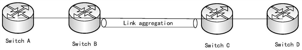
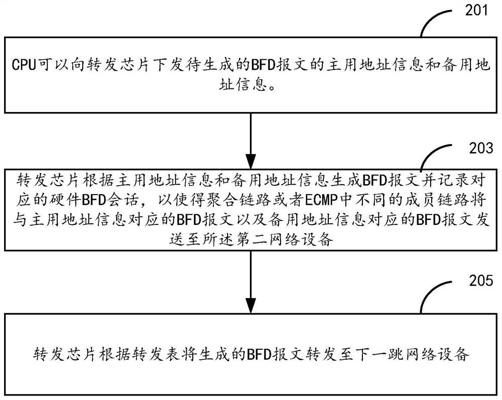
[0035] specific, image 3 It is a schematic flowchart of the BFD message forwarding method provided by the present disclosure. In this embodiment, the figure 1 The network diagram shown in the example is used as an example to describe the BFD packet forwarding method provided in this embodiment. BFD packets can be used for single-hop detection or multi-hop detection. Single-hop detection refers to the IP connectivity detection of two directly connected devices, where "single-hop" refers to one IP hop; multi-hop detection refers to the detection of the link condition of any path between two devices, These paths may span many hops.

[0036] In this embodiment, the first network device is figure 1 In Switch A, the second network device is figure 1 Take SwitchD in the example as an example. Among them, an aggregation link or an ECMP link is established between Switch A and Switch D on Switch B and Switch C.

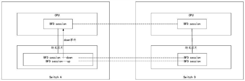
[0037] figure 2 A schematic diagram of establishing a BFD sessio...

Embodiment 2

[0057] On the basis of the foregoing embodiments, the method provided in this embodiment also includes:

[0058] Step 301: When the forwarding chip of Switch A detects that any hardware BFD session in the hardware BFD session corresponding to the CPU's software BFD session has timed out, the forwarding chip reports to the CPU a Down event indicating that the hardware BFD session timed out.

[0059] In an implementation manner, the hardware BFD sessions on the forwarding chip are respectively bound with timers, and the timers are used to identify whether the corresponding hardware BFD sessions time out.

[0060] Whether the hardware BFD has timed out, the specific judgment method is: judge whether the BFD message is received in 3 times the time interval (hello time). If the 3 times hello time timer does not receive a packet, the flag bit is set to 0, and a hardware BFD DOWN event is reported at the same time. Each time a BFD packet is received, the timer is cleared and restart...

Embodiment 3

[0068] On the basis of the foregoing embodiments, the present disclosure further provides a network device, configured to perform the method performed by the first network device in the foregoing Embodiment 1. Figure 4 Schematic diagram of the network equipment provided for this disclosure, such as Figure 4 As shown, the network equipment includes:

[0069] Forwarding chip 403, CPU401 and memory 402;

[0070] Wherein, the memory 402 is used to store program instructions;

[0071] The CPU 401 is configured to call the stored program instructions in the memory 402 to perform the following operations: send the primary address information and the standby address information of the BFD message to be generated to the forwarding chip 403, wherein the primary The address information is different from the source port number of the backup address information, and the other address information is the same;

[0072] The forwarding chip 403 generates a BFD message according to the act...


PUM


Abstract

The present specification provides a forwarding method of a bidirectional forwarding detection (BFD) message and a network device. The method comprises the steps: sending a standby BFD message on a forwarding chip of a source node of BFD detection, so when the BFD message is forwarded through an aggregation link or an equivalent multipath ECMP link, sending the BFD message corresponding to the main address information and the BFD message corresponding to the standby address information through different member links of the aggregation link or the equivalent multipath ECMP link, and when a member link in the aggregation link or the equivalent multipath ECMP link fails, forwarding the message through other member links which do not fail; therefore, the down event cannot be reported on the software level of the CPU, and the oscillation of the BFD session cannot occur.

Description

technical field [0001] This specification relates to the technical field of fault detection of network equipment, and in particular to a forwarding method and network equipment for bidirectional forwarding detection BFD messages. Background technique [0002] The device implements hardware bidirectional forwarding detection BFD (Bidirectional Forwarding Detection). The chip of the network device directly sends and receives BFD packets, which can send BFD packets at intervals of 10 ms or even 1 ms, and can detect link faults faster and take countermeasures. But in such figure 1 There are problems in the application process of the scenario shown: [0003] Such as figure 1 As shown in the figure, Switch A and Switch D establish a BFD connection through the Link Aggregation Control Protocol LACP (Link Aggregation Control Protocol) link between Switch B and Switch C. Since the BFD handshake packets between Switch A and Switch D can only be After the Greek operation, forwarding...

Claims


Application Information

Patent Timeline
IPC IPC(8): H04L12/26H04L12/24H04L12/707H04L12/709H04L29/08H04L45/24H04L45/243
CPCH04L43/0817H04L43/50H04L41/0631H04L67/141H04L45/245H04L45/22
Inventor 徐昶
Owner 北京华三通信技术有限公司
Why Eureka
Try Eureka