Automatic variable power transmission mechanism of electric motor car

A technology of automatic speed change and transmission mechanism, which is applied to vehicle gearboxes, wheel transmissions, vehicle components, etc., and can solve problems such as impact, inconvenient operation, and easy damage to machinery

Inactive Publication Date: 2011-06-08
蔡旭阳
View PDF1 Cites 2 Cited by
  • Summary
  • Abstract
  • Description
  • Claims
  • Application Information

AI Technical Summary

Problems solved by technology

However, when the motor is adjusted to run at a low speed, its output power and torque are correspondingly reduced, making the electric vehicle weak during the uphill process. Chinese Patent Publication No. CN201050582Y discloses an electric transmission, and its electric transm

Method used


Image

  • Automatic variable power transmission mechanism of electric motor car
  • Automatic variable power transmission mechanism of electric motor car
  • Automatic variable power transmission mechanism of electric motor car

Examples


Embodiment 1

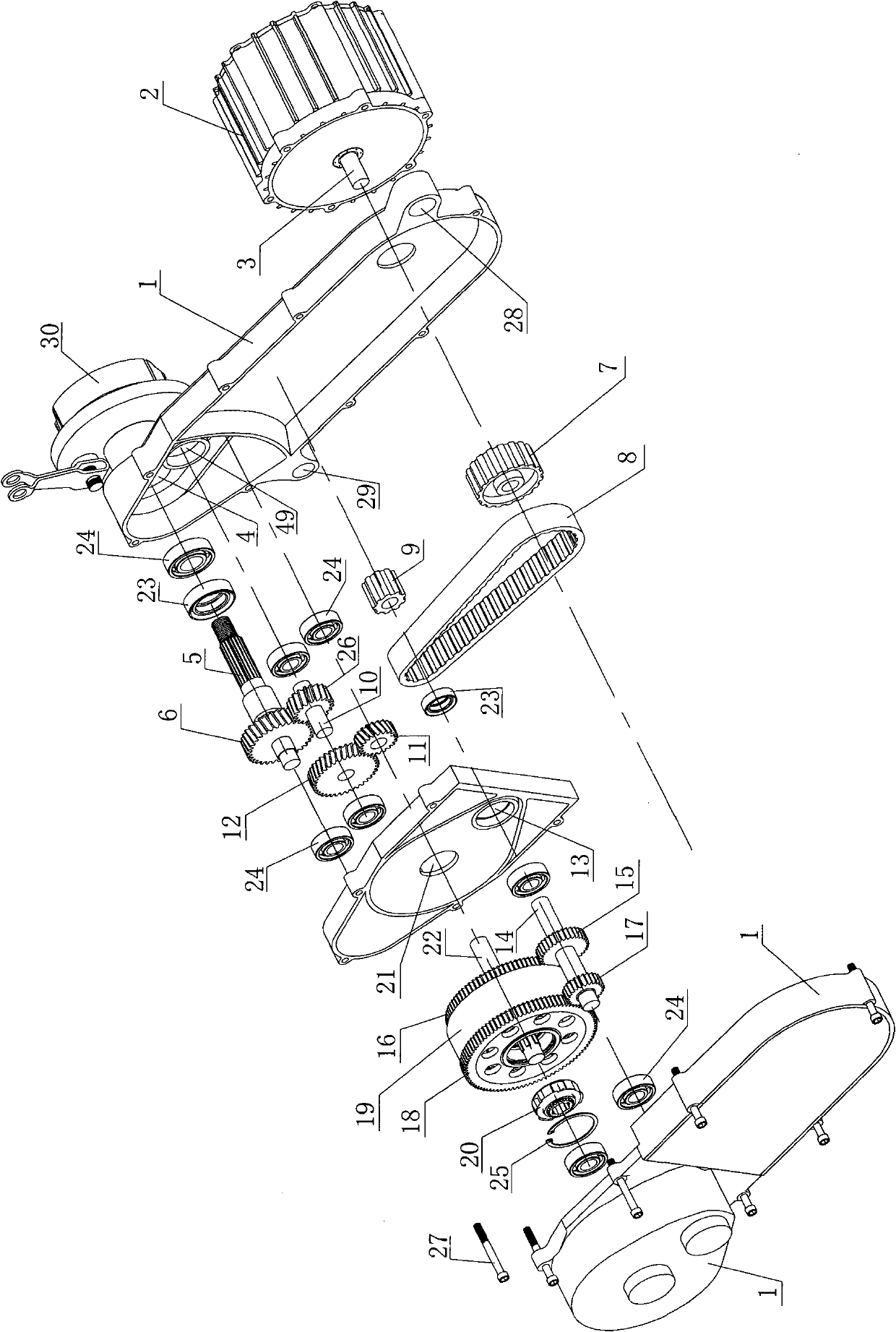
[0026] Such as Figure 1-Figure 9 Shown is the first embodiment of the invention of the electric vehicle power automatic transmission mechanism, the electric vehicle power automatic transmission mechanism includes a box body 1, the box body 1 is provided with a frame connection hole 28, and the vehicle frame connection hole 28 Used to fix the whole machine on the frame. The motor 2 is fixed on the wall of the casing 1 side with bolts, and the inner wall is respectively provided with an input shaft hole 13, an output shaft hole 21, a wheel shaft transmission hole 4, and an intermediate shaft hole 49, and the holes are respectively provided with Bearing 24, the inner hole of the bearing 24 is respectively provided with input shaft 14, output keyway shaft 22, intermediate shaft 10, wheel shaft 5, the high and low speed driving gear is fixed on the input shaft 14, and the high and low speed driving gear meshed with the high and low speed driving gear The driven gear is movable on...

Embodiment 2

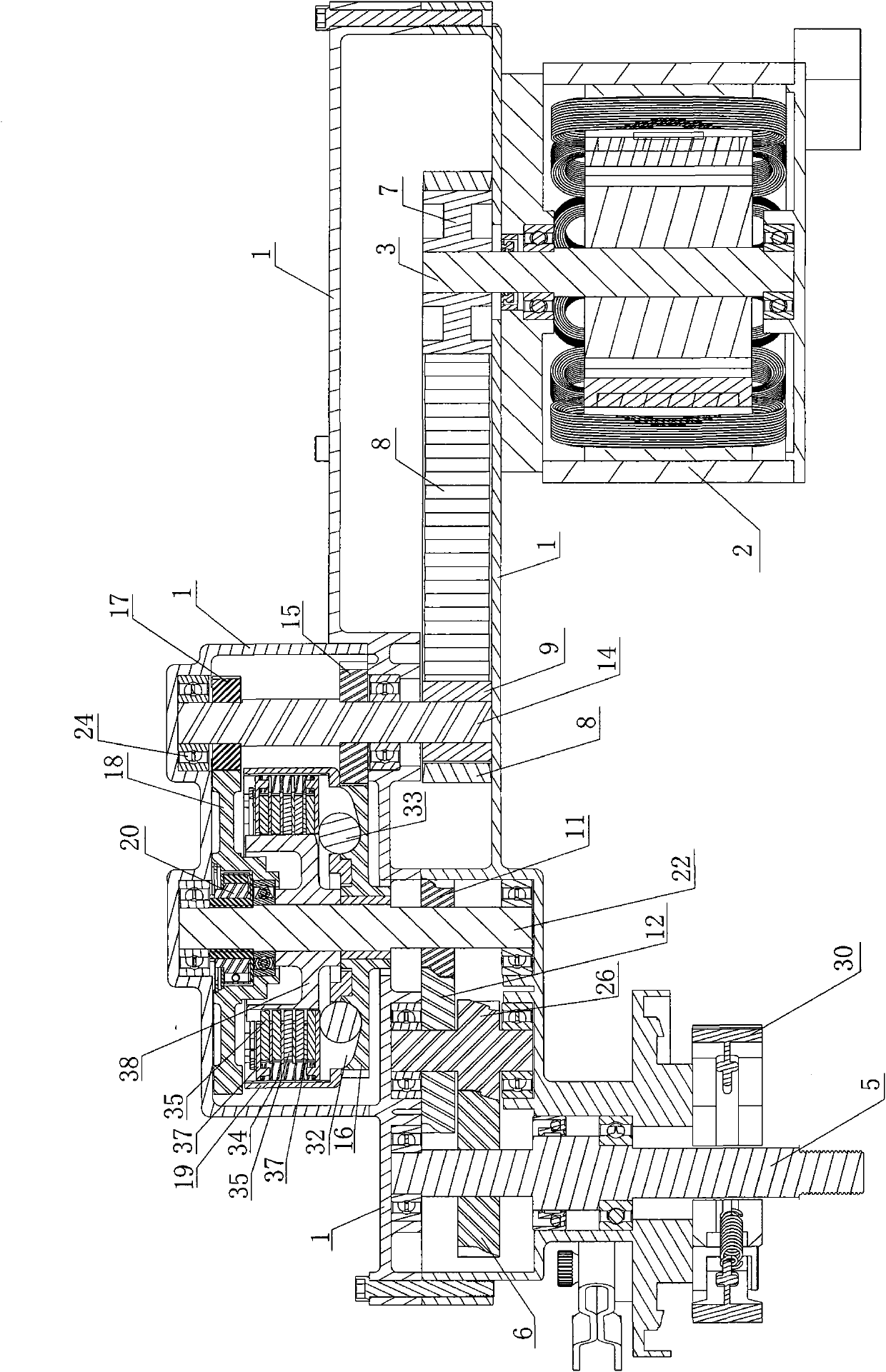
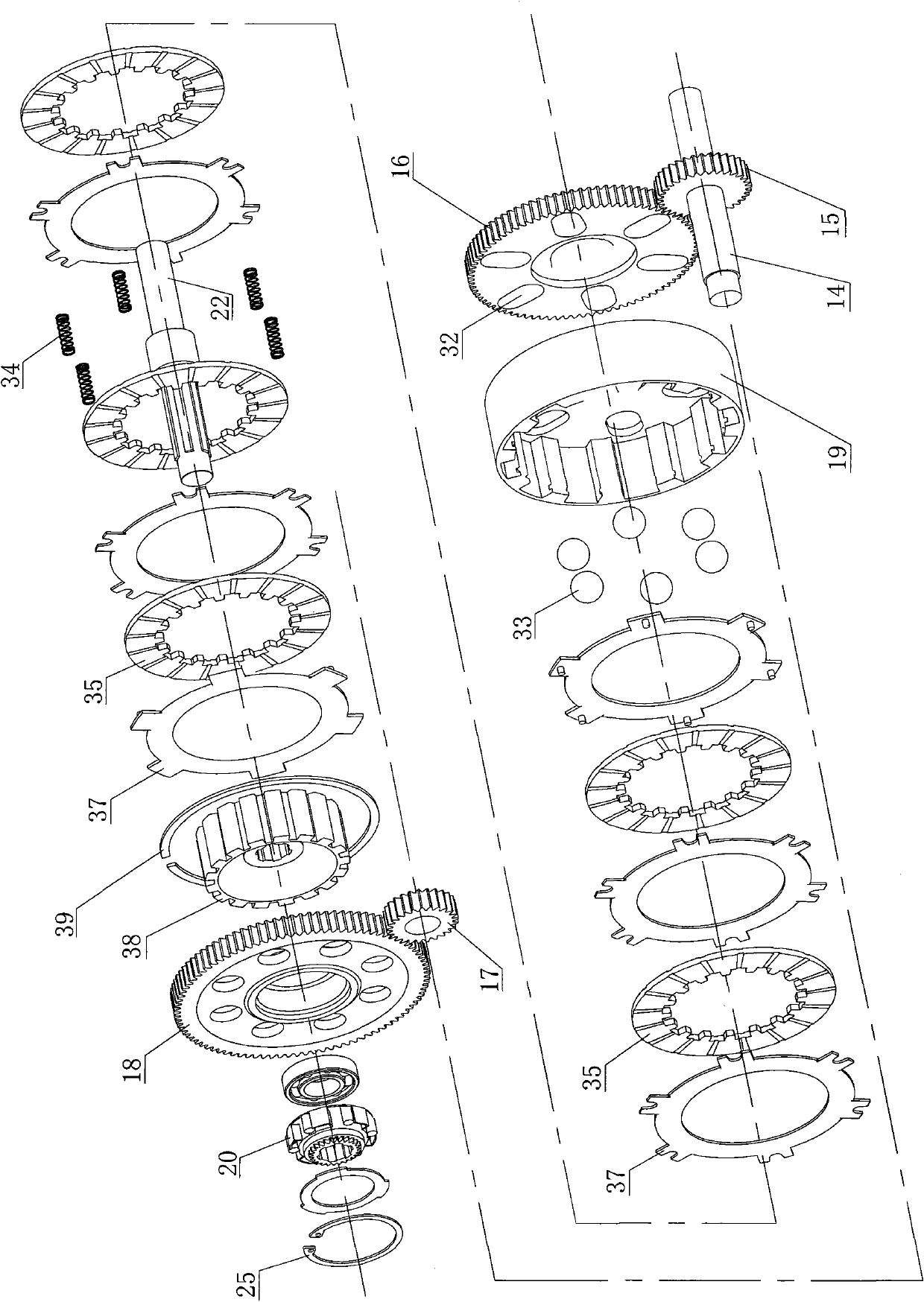
[0032] Such as Figure 10 , 11 Shown in is the second embodiment of the electric vehicle power automatic transmission mechanism of the present invention. The electric vehicle power automatic transmission mechanism includes a box body 1, the box body 1 is provided with a frame connecting hole 28, and the vehicle frame Connecting hole 28 is used for whole machine is fixed on the vehicle frame. The motor 2 is fixed on the wall of the casing 1 side with bolts, and the inner wall is respectively provided with an input shaft hole 13, an output shaft hole 21, a wheel shaft transmission hole 4, and an intermediate shaft hole 49, and the holes are respectively provided with Bearing 24, the inner hole of the bearing 24 is respectively provided with input shaft 14, output keyway shaft 22, intermediate shaft 10, wheel shaft 5, high-speed driving gear 15 is fixed on the input shaft 14, low-speed driving gear 17 passes through one-way bearing 31 The rotation is arranged on the input shaft...


PUM


Abstract

The invention belongs to the technical field of the power transmission of an electric motor car, in particular to an automatic variable power transmission mechanism of an electric motor car, comprising a box body, and a motor is arranged on the side wall of the box body and is provided with a motor shaft. The box body is internally provided with an input shaft, an output keyway shaft and an axle, wherein the motor shaft is in transmission connection with the input shaft; the output keyway shaft is in transmission connection with the axle; the input shaft is provided with a high-speed driving gear and a low-speed driving gear; the output keyway shaft is provided with a clutch on which a high-speed driven gear is fixed, a one-way driver is arranged between the output keyway shaft and the low-speed driven gear, the output keyway shaft is provided with a driven keyway sleeve, a driven friction sheet and a driving friction sheet are arranged between the driven keyway sleeve and the clutch, a driving-driven keyway sleeve separating spring is arranged on the end surfaces of the friction sheets, a slope groove is arranged between either friction sheet and the bottom end of the clutch, an eccentric bead is arranged in the slope groove, and an eccentric axial repulsion mechanism is formed by the slope groove and the eccentric bead.

Description

technical field [0001] The invention belongs to the technical field of electric vehicle power transmission Background technique [0002] The driving power of the existing electric vehicle is mainly changed by adjusting the voltage and current input to the motor and changing the speed of the motor. However, when the motor is adjusted to run at a low speed, its output power and torque are correspondingly reduced, making the electric vehicle weak during the uphill process. Chinese Patent Publication No. CN201050582Y discloses an electric transmission, and its electric transmission is manually adjusted for shifting operation. Inconvenient, in addition, because the gear is rigidly combined when the electric transmission shifts gears, there is a sense of impact when shifting gears, which can easily damage the machinery and make the driver feel uncomfortable. Contents of the invention [0003] The purpose of the present invention is to provide a simple structure, small size, fle...

Claims


Application Information

Patent Timeline
IPC IPC(8): B62M11/04
Inventor 蔡贵席
Owner 蔡旭阳
Why Eureka
Try Eureka