Anti-seepage coating and preparation process thereof
A preparation process and coating technology, which is applied in coatings, mixers, mixers with rotating stirring devices, etc., can solve problems such as low stirring efficiency and affecting use
- Summary
- Abstract
- Description
- Claims
- Application Information
AI Technical Summary
Problems solved by technology
Method used
Image
Examples
specific Embodiment approach 1
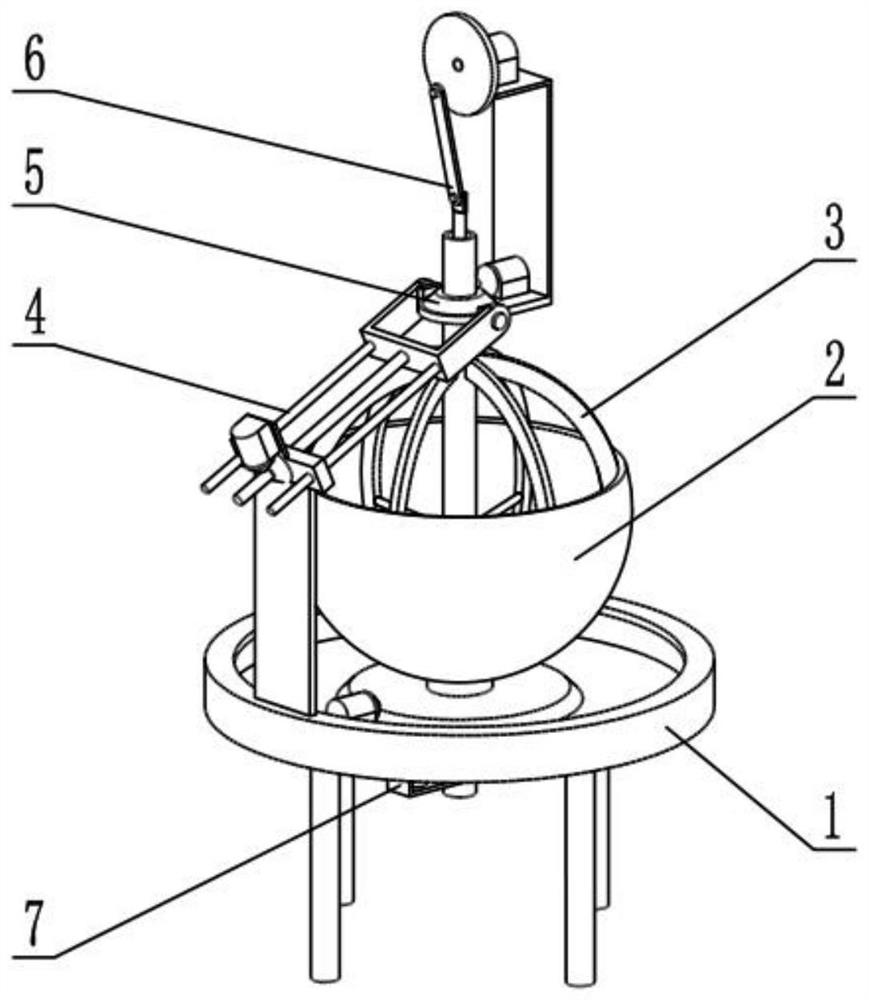
[0035] Such as Figure 1-11 Shown, a kind of anti-seepage coating preparation technology comprises the following steps:
[0036] Step 1, the raw materials are weighed in proportion and prepared;
[0037] Step 2, mixing and stirring all the raw materials;
[0038] Step 3, after the stirring is completed, pack and store;
[0039] The above-mentioned anti-seepage coating preparation process also relates to an anti-seepage coating preparation device;
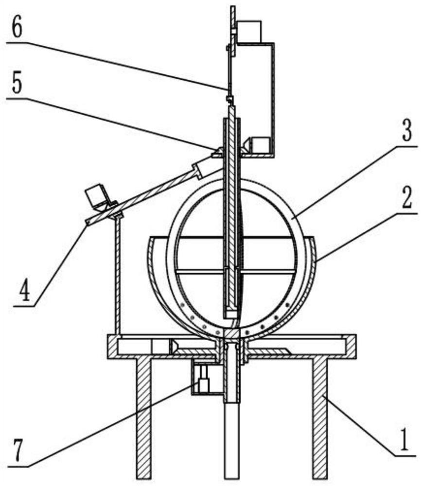
[0040] Described a kind of anti-seepage paint preparation device comprises support frame 1, mixing box 2, stirring mechanism 3, angle adjustment mechanism 4, stirring power mechanism 5, suction spraying mechanism 6 and discharge mechanism 7, and described mixing box 2 is connected in On the support frame 1, the stirring mechanism 3 is rotatably connected in the mixing box 2, the angle adjustment mechanism 4 is connected to the side end of the support frame 1, and the stirring power mechanism 5 is rotatably connected to the angle ...
specific Embodiment approach 2
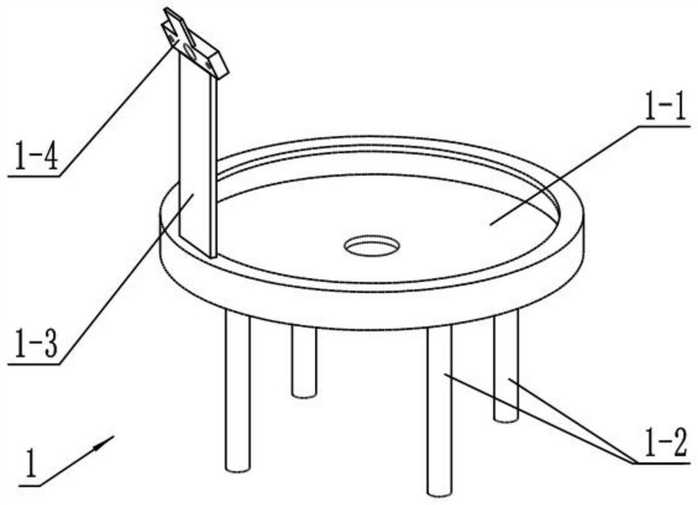
[0043] Such as Figure 1-11 As shown, the support frame 1 includes a bearing plate 1-1, a leg 1-2, a support plate 1-3 and a mounting seat 1-4, and the lower end surface of the bearing plate 1-1 is fixedly connected with four legs 1 -2, the lower end of the support plate 1-3 is fixedly connected to the side end of the bearing plate 1-1, and the mounting base 1-4 is obliquely fixedly connected to the upper end of the support plate 1-3.
specific Embodiment approach 3
[0045] Such as Figure 1-11 As shown, the mixing box 2 includes a hemispherical box 2-1, a lower discharge pipe 2-2, a transmission wheel 2-3 and a mixing motor 2-4, the inside of the hemispherical box 2-1 is a spherical structure, and the hemispherical The upper end of the box body 2-1 is open, the lower discharge pipe 2-2 is fixedly connected to the lower end of the hemispherical box body 2-1, the transmission wheel 2-3 is fixedly connected to the lower discharge pipe 2-2, and the lower discharge pipe 2-2 2 is rotatably connected to the center of the carrier disc 1-1, and the hybrid motor 2-4 is fixedly connected to the carrier disc 1-1 and is connected in transmission with the transmission wheel 2-3.
[0046]After the lower discharge pipe 2-2 is blocked by the discharge mechanism 7, the raw material is filled with the hemispherical box 2-1, and the mixing motor 2-4 is started to drive the transmission wheel 2-3 to make the hemispherical box 2-1 rotate. Stirring mechanism 3...
PUM
 Abstract
Description
Claims
Application Information
 - R&D
- Intellectual Property
- Life Sciences
- Materials
- Tech Scout
- Unparalleled Data Quality
- Higher Quality Content
- 60% Fewer Hallucinations
Browse by: Latest US Patents, China's latest patents, Technical Efficacy Thesaurus, Application Domain, Technology Topic, Popular Technical Reports.
© 2025 PatSnap. All rights reserved.Legal|Privacy policy|Modern Slavery Act Transparency Statement|Sitemap|About US| Contact US: help@patsnap.com


