Knuckle edge cutting, hole extruding and correcting composite die and design method thereof

A composite die and steering knuckle technology, applied in the direction of perforation tools, manufacturing tools, metal processing equipment, etc., can solve the problems of unevenness, unstable die structure, easy sticking of forgings, cutting edge and upper die, etc.

Active Publication Date: 2021-05-04
HUBEI TRI RING FORGING +1
View PDF10 Cites 1 Cited by
  • Summary
  • Abstract
  • Description
  • Claims
  • Application Information

AI Technical Summary

Problems solved by technology

[0003] The existing steering knuckle trimming dies have the following technical problems. The structure of the steering knuckle forging is relatively complicated, and its parting surface is a spatial curved surface. Correspondingly, the flash is also a spatial curved surface. It is difficult to accurately locate when trimming, and As a result, there is a large misalignment force during edge trimming, and the trimming marks are large and uneven; on the other hand, in order to improve material utilization, the draft angle of the steering knuckle forging is small, which makes the forging easy to stick to the upper die at the trimming edge, and the process is not good. Smooth; thirdly, the center hole of the steering knuckle forging needs to be processed for the subsequent process. In the prior art, the center hole cannot be formed in the final forging. Cost of production
[0004] In recent years, some trimming and correction composite mold structures have appeared, but this type of mold structure still cannot meet the requirements of trimming, center hole pressing, and correction of complex steering knuckle forgings. In addition, this type of mold structure is unstable in practice. , the process is not smooth

Method used


Image

  • Knuckle edge cutting, hole extruding and correcting composite die and design method thereof
  • Knuckle edge cutting, hole extruding and correcting composite die and design method thereof

Examples


Embodiment Construction

[0033] The present invention will be described in further detail below in conjunction with the accompanying drawings and specific embodiments, and the implementation scope of the present invention is not limited thereto.

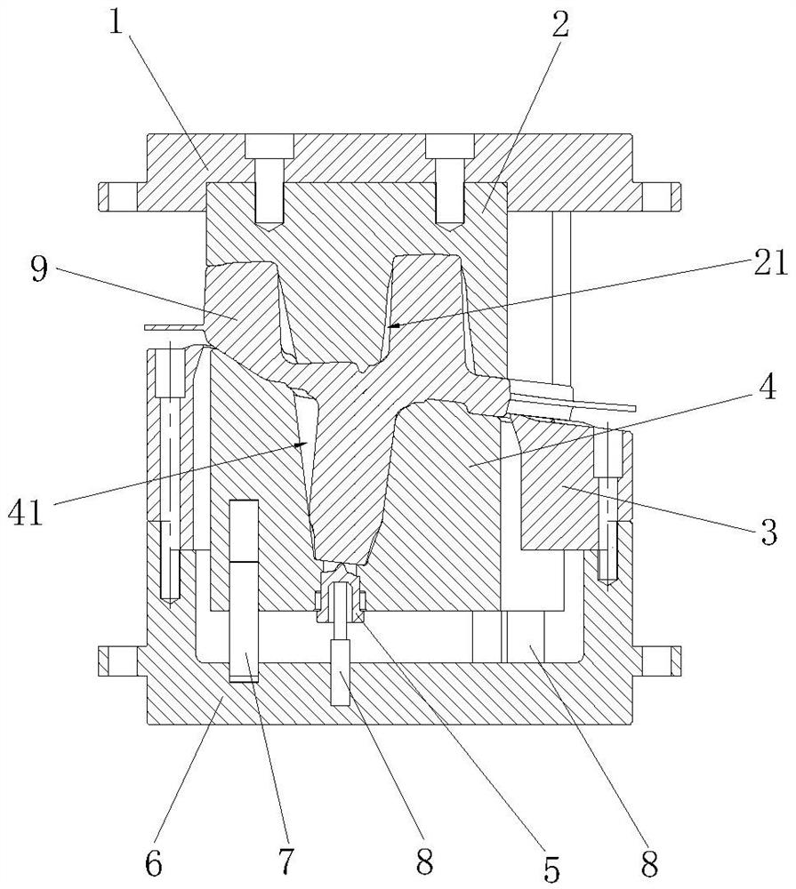
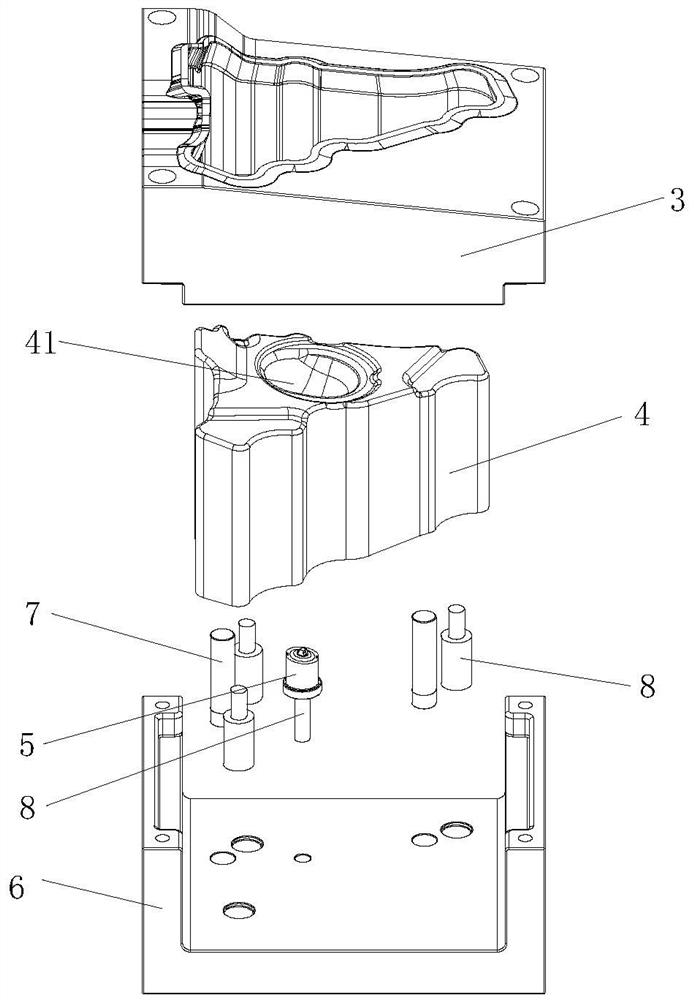
[0034] like figure 1 , figure 2 As shown, the steering knuckle trimming, extrusion, and correction composite mold of the present embodiment include an upper die and a lower die, the upper die includes an upper die base 1, a trimming upper die 2, and the lower die includes a lower die base 6, a trimming Lower die 3, lower die core 4, the lower side of the trimming upper die 2 is provided with an upper die cavity 21 corresponding to the ears and discs of the steering knuckle forging, the trimming lower die 3 is located on the trimming A lower die core 4 is provided directly below the upper die 2, and a lower die cavity 41 corresponding to the stem and disc of the steering knuckle forging is arranged on the upper side of the lower die core 4. The inclination ...


PUM


Abstract

The invention relates to the technical field of knuckle forging dies, in particular to a knuckle edge cutting, hole extruding and correcting composite die and a design method thereof. The knuckle edge cutting, hole extruding and correcting composite die comprises an upper die base, an upper edge cutting die, a lower edge cutting die, a lower die core, a lower die base, a guide column, an ejector rod and a spring. In the working process of the composite die, the functions of knuckle forge piece edge cutting, center hole pressing and correction are achieved in sequence; by using the composite die, the production procedures of a knuckle forge piece are reduced, and the machining period of the knuckle forge piece is shortened; by correcting the knuckle forge piece, the contour quality of the forge piece is improved; a center hole of the knuckle forge piece is subjected to coining in the lower die core, and the precision of the center hole of the knuckle forge piece is improved; and in addition, as the contour precision and the center hole precision of the knuckle forge piece are improved, the machining allowance of the knuckle forge piece is small, and the material utilization rate of the knuckle forge piece is improved.

Description

technical field [0001] The invention relates to the technical field of steering knuckle forging dies, in particular to a steering knuckle trimming, hole extrusion, correction composite die and a design method thereof. Background technique [0002] Steering knuckle, also known as "horns" because of its shape, is one of the important parts in the steering axle of a car, which can make the car run stably and transmit the driving direction sensitively. The function of the steering knuckle is to transmit and bear the front load of the car, support and drive the front wheel to rotate around the kingpin to turn the car. When the car is running, it bears variable impact loads, so it is required to have high strength. With the rapid development of my country's automobile industry, the production and R&D of steering knuckle products has also developed rapidly, and the types of steering knuckles have become diverse. Therefore, more advanced and complete mold structures are also requir...

Claims


Application Information

Patent Timeline
Patent Type & Authority Applications(China)
IPC IPC(8): B21D28/14B21D28/04B21D28/34B21D43/28B21K27/06B21K27/00
CPCB21D28/14B21D28/04B21D28/34B21D43/28B21K27/06B21K27/00Y02P70/10
Inventor 张运军周杰武建祥陈天赋彭海军杨杰汪西屈志远许恢兵牛洪波
Owner HUBEI TRI RING FORGING
Why Eureka
Try Eureka