Connection robot with adjusting mechanism for automatic production and application of connection robot
An adjustment mechanism and robot technology, applied in metal processing and other directions, can solve the problems of inability to adjust the length, inability to manufacture in large quantities, and inability to adapt the connection table to the production line, etc., to achieve the effect of improving the use effect and improving the convenience.
- Summary
- Abstract
- Description
- Claims
- Application Information
AI Technical Summary
Problems solved by technology
Method used
Image
Examples
Embodiment 1
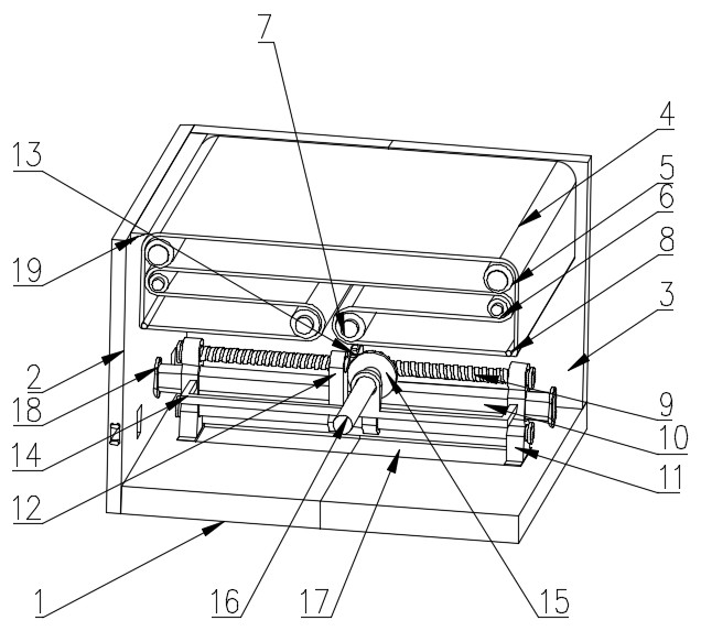
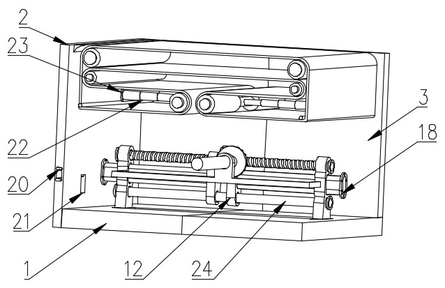
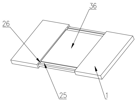
[0037] see Figure 1-8, a connecting robot for automatic production with an adjustment mechanism, including a bottom plate 1 and a conveyor belt 4, a side plate 2 is fixedly installed on the upper surface of the bottom plate 1, a vertical plate 3 is fixedly installed on one side of the vertical end of the side plate 2, and the vertical The outer wall of the plate 3 is fixedly connected with the bottom plate 1, the vertical plate 3 and the inner wall of the bottom plate 1 are slidingly connected with a plate core 36, the upper surface of the bottom plate 1 is slidably connected with the bearing seat 11 through the chute 17, and the inner wall of the bearing seat 11 rotates respectively The two-way threaded rod 9 and the slide rod 24 are connected, and the outer wall of the two-way threaded rod 9 is threadedly connected with a threaded sleeve 12 through a thread groove. The connecting rod 10 is fixedly installed, and the end of the connecting rod 10 away from the threaded sleeve...
Embodiment 2
[0041] see Figure 7 , the side plate 2 is provided with a socket 21 in the horizontal direction, and the inner surface wall of the side plate 2 is slidably connected with an insertion rod 33, and the lower surface of the insertion rod 33 is fixedly equipped with a baffle plate 37, and one end of the insertion rod 33 is fixedly installed with a handle 34, and the handle 34 Vertical direction is provided with pin hole, and side plate 2 vertical end one side is fixedly installed with pin seat 20, and side plate 2 vertical end outer wall is fixedly installed with clamping block 35, and clamping block 35 outer wall is provided with groove.
[0042] When the user needs to splice and cooperate with multiple docking platforms according to actual needs, the insertion rod 33 is pulled out a part, and then another docking platform is approached, and the locking block on the side of the vertical end of the side plate 2 35 into the socket 21 on the side plate 2, and then push the insertio...
Embodiment 3
[0045] see Figure 4 The outer wall of the transmission shaft 16 is connected to the vertical plate 3 in rotation, and a fixed rod 32 is fixedly installed at one end of the transmission shaft 16. The inner surface wall of the fixed rod 32 is elastically connected to the hand wheel 27 by a spring 30, and the vertical end of the hand wheel 27 is close to the fixed rod 32. A sleeve rod 31 is fixedly installed on one side, and the outer wall of the sleeve rod 31 is slidingly connected with the inner surface wall of the fixed rod 32. The side of the vertical end of the hand wheel 27 close to the fixed rod 32 is fixedly installed with a second ring gear 29, and the fixed rod 32 passes through the The first ring gear 28 fixedly installed at one end is meshed with the handwheel 27, and the outer wall of the handwheel 27 is provided with an arc-shaped groove.
[0046] In order to prevent the handwheel 27 from accidentally turning and causing unnecessary losses, a self-locking mechanism...
PUM
 Abstract
Description
Claims
Application Information
 - R&D
- Intellectual Property
- Life Sciences
- Materials
- Tech Scout
- Unparalleled Data Quality
- Higher Quality Content
- 60% Fewer Hallucinations
Browse by: Latest US Patents, China's latest patents, Technical Efficacy Thesaurus, Application Domain, Technology Topic, Popular Technical Reports.
© 2025 PatSnap. All rights reserved.Legal|Privacy policy|Modern Slavery Act Transparency Statement|Sitemap|About US| Contact US: help@patsnap.com


