Small-spacing visual region guiding type three-dimensional display system and method

A three-dimensional display and guidance technology, applied in the direction of the instrument, to achieve the effect of overcoming the focus-convergence conflict and improving the comfort of three-dimensional vision

Active Publication Date: 2021-05-04
驻景(广州)科技有限公司
View PDF5 Cites 3 Cited by
  • Summary
  • Abstract
  • Description
  • Claims
  • Application Information

AI Technical Summary

Problems solved by technology

The traditional stereoscopic technology of monocular single view, the visual fatigue caused by its inherent focus and convergence conflict is the bottleneck problem faced by the 3D display industry, and it is urgent to break through

Method used


Image

  • Small-spacing visual region guiding type three-dimensional display system and method
  • Small-spacing visual region guiding type three-dimensional display system and method
  • Small-spacing visual region guiding type three-dimensional display system and method

Examples


Embodiment 1

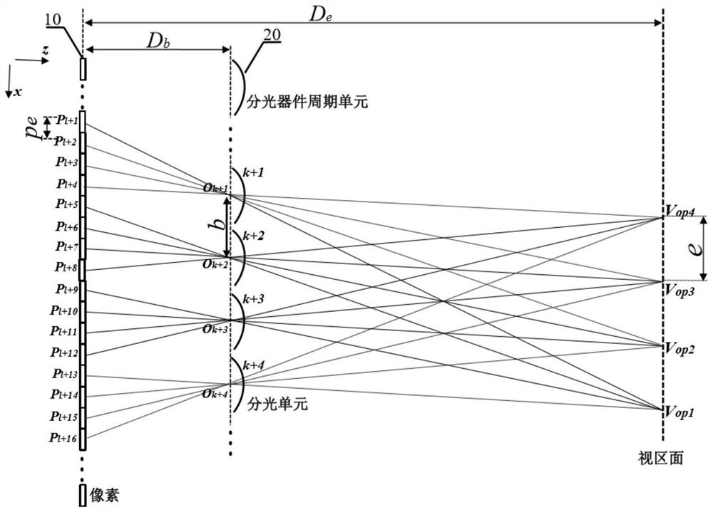
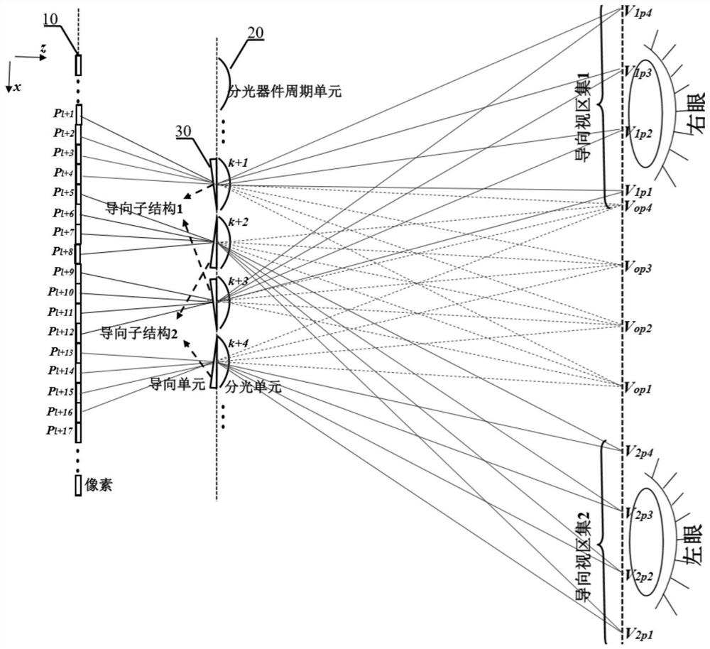
[0065] like image 3 , taking the cylindrical lens grating and generating 4 initial viewing areas as an example, along the transmission direction of the light emitted by the 10 pixels of the display screen, the light splitting device 20 is placed in front of the display screen 10, and based on the principle of light splitting, the initial viewing area V is generated op1 , V op2 , V op3 , and V op4 . When only the display screen 10 and the light splitting device 20 exist, the pixel P of the display screen 10 l+1 ,P l+5 ,P l+9 ,P l+13 , ... The pixel group formed by the initial viewing area V op1 Visible inside, pixel P l+2 ,P l+6 ,P l+10 ,P l+14 , ... The pixel group formed by the initial viewing area V op2 Visible inside, pixel P l+3 ,P l+7 ,P l+11 ,P l+15 , ... The pixel group formed by the initial viewing area V op3 Visible inside, pixel P l+4 ,P l+8 ,P l+12 ,P l+16 , ... The pixel group formed by the initial viewing area V op4 Visible inside. The guid...

Embodiment 2

[0070]Using the timing-controllable optical splitting device 20 and / or the timing-controllable guiding device 30 , at M adjacent time points with an interval of Δt / M, M groups of different pairs of optical splitting units 20 and guiding units 30 appear cyclically in sequence. The guiding device 30 at each time point is composed of L groups of guiding substructures, and each guiding unit of the guiding device 30 is in one-to-one correspondence with each optical splitting device of the light splitting device 20, forming a light splitting unit-guiding unit pair. Then more L×M guiding viewport sets can be formed within Δt time by means of time division multiplexing. like Figure 5 , taking L=2 and M=2 as an example. At the time point T within the time period T~T+Δt, similar to the process described in Embodiment 1, through L=2 guide substructures, two guide viewport sets are generated, guide viewport set 1 and guide viewport set 2. Then, at the time point T+Δt / 2 within the time...

Embodiment 3

[0078] In the above system, a switch device 40 composed of N groups of controllable switch apertures may be further introduced. Similarly, the light splitting device 20 is placed in front of the display screen 10 along the transmission direction of the light emitted by the pixels of the display screen 10 . Introducing the guiding device 30 and the switching device 40, the guiding unit of the guiding device 30, the apertures of the switching device 30 and the splitting unit of the splitting device 20 correspond one-to-one in real time, and the splitting device 20 and the splitting device 30 corresponding in real time The unit and the guiding unit form a light splitting unit-guiding unit pair. Each component aperture of the switch device 40 is divided into N groups, and within a time period of Δt, one group of the N groups of apertures of the switch device 40 is turned on, and the light splitting unit-guiding unit pair corresponding to the group of apertures is selected. Specif...


PUM


Abstract

The invention relates to the technical field of three-dimensional image display, in particular to a small-spacing visual region guiding type three-dimensional display system and method. The small-spacing visual region guiding type three-dimensional display system comprises a display screen, a light splitting device, a guiding device, a control unit, a selectable switching device, a diaphragm array, a tracking feedback unit and an orthogonal gating control device, wherein the light splitting device is used for guiding emergent light of different groups of pixels on the display screen to be visible to different initial visual regions respectively; under the assistance of other system components, the arranged guiding device deflects different pixel subsets of the pixel group corresponding to each initial visual region to emit light to each corresponding guiding visual region in the different guiding visual region set; and guide visual region sets are used for covering different eyes of an observer, and the distance between every two adjacent guide visual region sets is not larger than the pupil diameter of the observer. According to the small-spacing visual region guiding type three-dimensional display system and the method, through monocular multi-view presentation, focusing-convergence conflicts can be overcome, three-dimensional display capable of achieving natural focusing is achieved, and the three-dimensional visual comfort degree is improved.

Description

technical field [0001] The present invention relates to the technical field of three-dimensional image display, and more particularly, to a small-pitch viewing zone-guided three-dimensional display system and method. Background technique [0002] Because two-dimensional display is difficult to clearly and accurately express the depth information of the third dimension, people have been working on the research of display technology that can display three-dimensional scenes - three-dimensional image display technology. Multi-view based on spectroscopic principle Figure three The three-dimensional display technology is compatible with the mainstream flat panel display, and is the most widely used three-dimensional display technology at present: through light-splitting devices such as gratings, the outgoing light of different groups of pixels on the display screen is guided to different viewing areas distributed equidistantly, so that different viewing areas can see Each corres...

Claims


Application Information

Patent Timeline
Patent Type & Authority Applications(China)
IPC IPC(8): G02B30/30G02B30/27
Inventor 刘立林滕东东
Owner 驻景(广州)科技有限公司
Why Eureka
Try Eureka