Steaming exhaust structure and electric steam box with same

A technology for steaming and exhausting steam, which is applied in the field of electric steamers and can solve problems such as the reduction of steam condensation effect.

Pending Publication Date: 2021-05-07
NINGBO FOTILE KITCHEN WARE CO LTD
View PDF1 Cites 2 Cited by
  • Summary
  • Abstract
  • Description
  • Claims
  • Application Information

AI Technical Summary

Problems solved by technology

However, the heat dissipation plate of the existing condensation cavity is effective in cooling the steam. After the electric steamer works for 3 to 4 minutes, the heat dissipation plate will quickly heat up to a higher temperature, thereby greatly reducing the condensation effect of the steam.

Method used


Image

  • Steaming exhaust structure and electric steam box with same
  • Steaming exhaust structure and electric steam box with same
  • Steaming exhaust structure and electric steam box with same

Examples


Embodiment 1

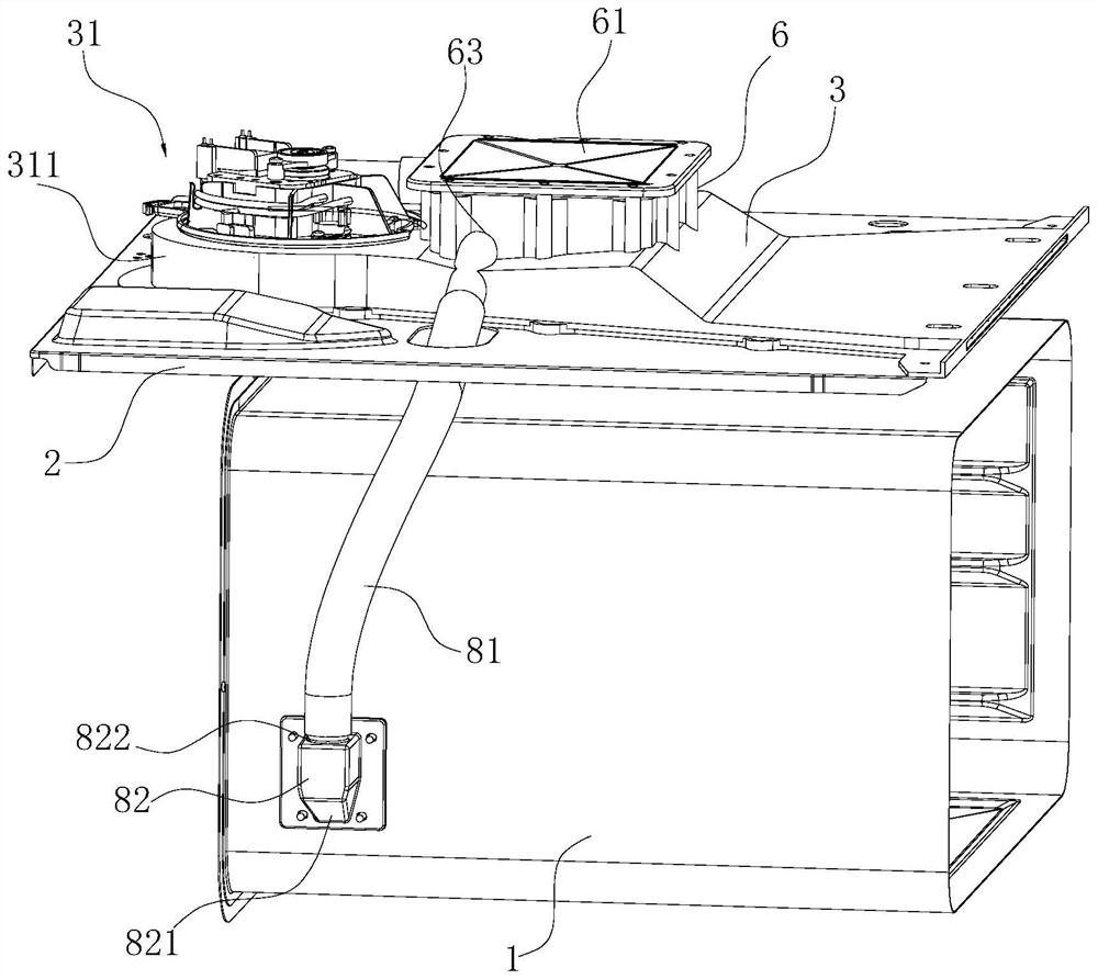
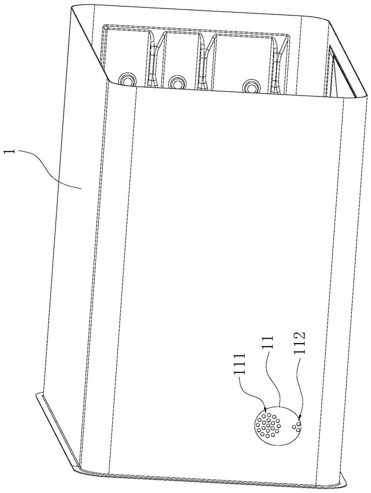
[0040] Such as Figure 1~6 As shown, an electric steamer includes a steaming exhaust structure, the steaming exhaust structure includes an inner tank 1, an upper mounting plate 2 is arranged above the inner tank 1, and the upper mounting plate 2 is covered with a The wind deflector 3, the heat dissipation channel 30 is surrounded between the wind deflector 3 and the upper surface of the upper mounting plate 2, and the upper cover of the wind deflector 3 is provided with a square condensation cover 6, and the condensation cover 6 and the wind deflector The upper surface of 3 encloses a condensation chamber 60, wherein, the steam inlet 63 of the above-mentioned condensation chamber 60 is in fluid communication with the steam exhaust port 11 of the above-mentioned liner 1 (the phase fluid communication here can have multiple realizations: when the condensation When the steam inlet 63 of the cavity 60 is adjacent to the steam exhaust port 11 of the inner bag 1, the two can be dire...

Embodiment 2

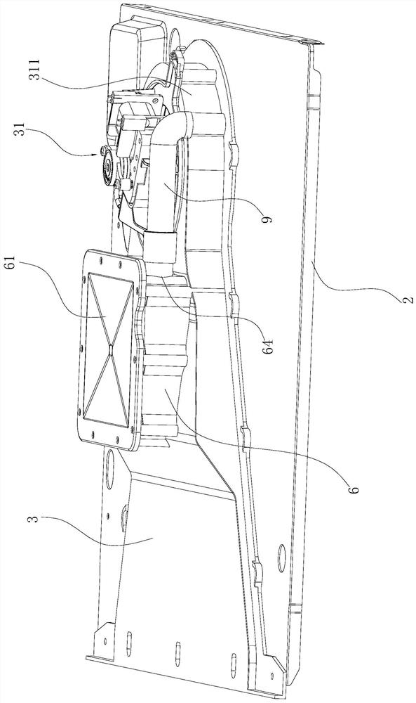
[0049] Such as Figure 7-9 As shown, different from Embodiment 1, the first air channel 30A can be opened and closed in this embodiment, and, when the temperature of the second cooling plate 62 is lower than the preset temperature (the preset temperature in this embodiment is When the second cooling plate 62 cannot condense the upper limit temperature of steam), the first air channel 30A is closed, and when the temperature of the second cooling plate 62 is higher than the preset temperature, the second air channel 30B is opened. Through the opening and closing of the first air passage 30A, on the one hand, when the temperature of the second cooling plate 62 is low, the exhaust gas entering the heat dissipation passage 30 can be concentrated through the second air passage through the closing of the first air passage 30A. 30B, thereby increasing the exhaust speed (by reducing the exhaust area to increase the air pressure inside the heat dissipation channel 30, thereby increasing...


PUM


Abstract

The invention relates to a steaming exhaust structure and an electric steam box with same; the steaming exhaust structure comprises an inner container and a heat dissipation channel, a condensation cavity is formed above the heat dissipation channel, a steam inlet of the condensation cavity is in fluid communication with a steam exhaust port of the inner container, the top wall of the condensation cavity is a first heat dissipation plate, the bottom wall of the condensation cavity is a second heat dissipation plate, and the second heat dissipation plate and the top wall of the heat dissipation channel are shared. A partition plate is transversely arranged in the heat dissipation channel in the direction from the air inlet to the air outlet of the heat dissipation channel and divides the heat dissipation channel into a first air channel and a second air channel in the vertical direction, and the second heat dissipation plate is located in the first air channel. Through the arrangement of the double heat dissipation plates, the condensation effect on high-temperature steam entering the condensation cavity can be improved. Besides, heat, transmitted to the second heat dissipation plate, of steam in the condensation cavity can be taken away through the first air channel, so that the second heat dissipation plate can be kept at a low temperature, the continuous condensation effect of the second heat dissipation plate on the steam can be guaranteed, and the overall condensation effect of the condensation cavity on the steam is improved.

Description

technical field [0001] The invention relates to the field of electric steamers, in particular to a steaming and exhaust structure and an electric steamer with the structure. Background technique [0002] An electric steamer is an electrical device that uses high-temperature steam to cook food, and the excess steam is discharged through the exhaust channel during the cooking process. The exhaust channel of the existing electric steamer is generally equipped with a condensing cavity structure, and the externally discharged steam condenses in the condensing cavity, which can reduce the amount of externally discharged steam on the one hand, and return the condensed water to the inner tank on the other hand Or re-evaporate in an external steam generator to realize the recycling of condensed water. For example, the Chinese invention patent with the application number CN201810615563.X (the application publication number is CN110604477A) discloses a steam discharge structure, which...

Claims


Application Information

Patent Timeline
Patent Type & Authority Applications(China)
IPC IPC(8): A47J27/04A47J36/38
CPCA47J27/04A47J36/38A47J2027/043
Inventor 郑伟
Owner NINGBO FOTILE KITCHEN WARE CO LTD
Why Eureka
Try Eureka