Massager for preventing lower limb deep vein thrombosis
A technology for deep vein thrombosis and massager, which is applied in roller massage, auxiliary products for massage, physical therapy, etc., can solve the problems of reducing massage effect, unable to lift patients, and reducing performance.
- Summary
- Abstract
- Description
- Claims
- Application Information
AI Technical Summary
Problems solved by technology
Method used
Image

Examples
Embodiment 1
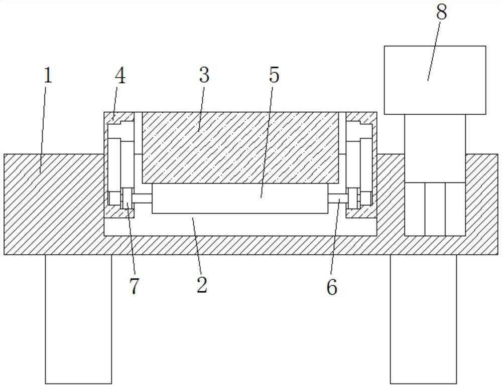
[0032] see Figure 1 to Figure 5 , the present invention provides a technical proposal for a massager for preventing deep vein thrombosis of lower extremities: a massager for preventing deep vein thrombosis of lower extremities, comprising a base 1, an active groove 2 is opened on the upper end surface of the base 1, and the inside of the active groove 2 A placement tube 3 and a roller 5 are provided, and the roller 5 is closely attached to the outer wall of the placement tube 3, side panels 4 are fixedly installed on both ends of the placement tube 3, and a placement frame 8 is provided on the upper end surface of the base 1 near one end. ;
[0033] The inside of the placement tube 3 is provided with a limiting groove 14, and a limiting plate 16 is slidably installed inside the limiting groove 14. A pressure bar 15 is fixedly installed on the side of the limiting plate 16, and a straight rod is fixedly installed on the other side of the limiting plate 16. 13. A spring 17 is ...
Embodiment 2
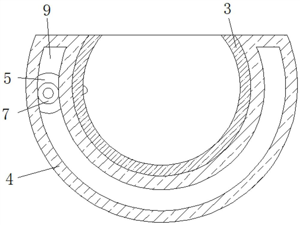
[0038] Such as Figure 1 to Figure 4 As shown, under the condition that other parts are all the same as in Embodiment 1, the difference between this embodiment and Embodiment 1 is that: the inside of the side plate 4 is provided with a tooth groove 9 and a guide groove 12, and the inner meshing connection of the tooth groove 9 is connected with Rotating gear 7, rotating shaft 6 runs through the central position of rotating gear 7 and cylinder 5, and the center position of one side of rotating gear 7 is fixedly connected with the output shaft of motor 10, and motor 10 is slidably installed in the inside of guide groove 12.
[0039] The tooth slots 9 on the two side plates 4 are symmetrical, and the two rotating teeth 7 are respectively located at both ends of the rotating shaft 6 .
[0040] Working principle: the motor 10 drives the rotating gear 7 to rotate, the rotating gear 7 drives the rotating shaft 6 to rotate, the rotating shaft 6 drives the roller 5 to rotate, and the r...
Embodiment 3
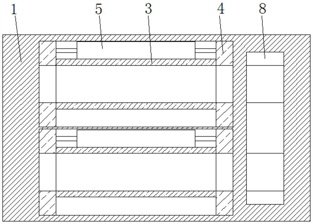
[0042] Such as Figure 5As shown, under the condition that other parts are the same as those in Embodiment 1, the difference between this embodiment and Embodiment 1 is that a storage groove 18 is provided on the upper end surface of the base 1 near one end, and the bottom end of the inner surface of the storage groove 18 is An electric push rod 19 is fixedly installed, and the placement frame 8 is fixedly installed on the upper end surface of the electric push rod 19 .
[0043] The upper end surface of the placement frame 8 is provided with a placement groove 11, which corresponds to the placement tube 3 one by one, and the two are located on the same center line.
[0044] The lower end surface of the base 1 near the corners is fixedly equipped with support feet, and the inner wall of the placement tube 3 and the inner wall of the placement groove 11 are all provided with rubber pads.
[0045] A specific application of this embodiment is: the patient's feet are placed on the...
PUM
 Abstract
Description
Claims
Application Information
 - R&D
- Intellectual Property
- Life Sciences
- Materials
- Tech Scout
- Unparalleled Data Quality
- Higher Quality Content
- 60% Fewer Hallucinations
Browse by: Latest US Patents, China's latest patents, Technical Efficacy Thesaurus, Application Domain, Technology Topic, Popular Technical Reports.
© 2025 PatSnap. All rights reserved.Legal|Privacy policy|Modern Slavery Act Transparency Statement|Sitemap|About US| Contact US: help@patsnap.com