Lifting type mobile catenary supporting device, mobile catenary and operation method
A catenary and lifting technology, applied in the direction of overhead lines, etc., can solve problems such as hidden safety hazards, achieve the effects of improving efficiency, improving economic and social benefits, and ensuring normal operation
- Summary
- Abstract
- Description
- Claims
- Application Information
AI Technical Summary
Problems solved by technology
Method used
Image
Examples
specific Embodiment 1
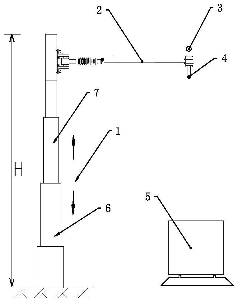
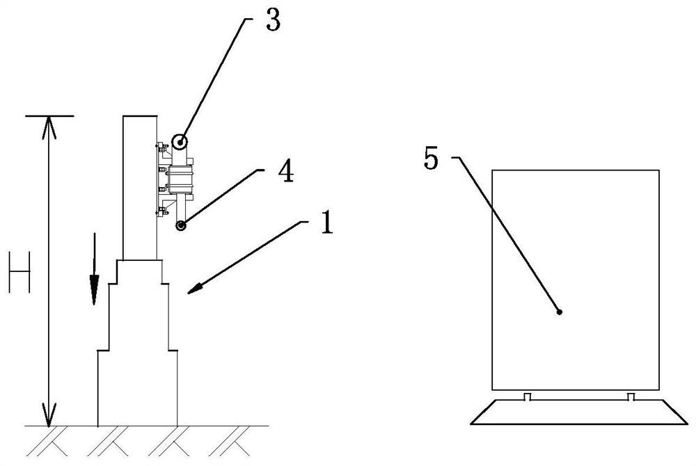
[0099] see figure 1 and figure 2 As shown, in this embodiment, the distance between the top of the variable-height support mechanism and the rail surface is variable, and the setting mechanism adopted is: the variable-height support mechanism includes a telescopic support mechanism, and the telescopic support mechanism The elongation of the mechanism drives the support mechanism to rise, and the retraction of the telescopic support mechanism drives the support mechanism to descend. The upper lifting unit 7 is accommodated in the lower lifting unit 6 in this embodiment. figure 1 The supporting mechanism is in the working position (on the top of the railway, the pantograph of the freight train 5 can take power from the contact wire 4), and the supporting mechanism adopts the rotating mode to move the catenary cable 3 and or the contact wire 4 to the non- Working position (one side of railway), support mechanism can adopt the mode of horizontal rotation, has and can adopt tele...
specific Embodiment 2
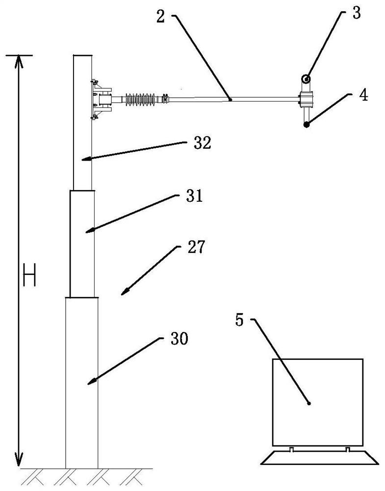
[0110] In this embodiment, the distance between the top of the variable-height support mechanism and the rail surface is variable, and the setting mechanism adopted is: the variable-height support mechanism includes a multi-level lifting mechanism, and the multi-level lifting mechanism rises Or fall, and drive the directly or indirectly set support institutions to rise or fall.
[0111] It should be added that the setting method of the multi-level lifting mechanism in this embodiment is as follows:
[0112] The lower end of the multi-stage lifting mechanism is arranged below the ground or in the artificial building foundation pit;
[0113] At least one level of the multi-level lifting mechanism is set below the ground or in the artificial building foundation pit; or
[0114] Part of the main body of at least the lowest level in the multi-level lifting mechanism is arranged below the ground or in the artificial building foundation pit.
[0115] In this embodiment, after the m...
specific Embodiment 3
[0118] Such as Figure 7 As shown, in this embodiment, the distance between the top of the variable-height support mechanism and the rail surface is variable, and the setting mechanism adopted is: the variable-height support mechanism is movably connected with the base 9, and on the base 9 A connecting piece 10 is provided, through which the height-variable support mechanism is movably connected with the base 9 . The height-variable support mechanism has a vertical state and a tilted state.
[0119] Include push-pull mechanism 11 in the present embodiment, as Figure 7 As shown, the push-pull mechanism is used to push the height-variable support mechanism to be in a vertical state, or as Figure 8 As shown, the pushing mechanism is also used to pull the height-variable support mechanism to fall down and be in a dumped state. The pushing mechanism adopts an electric pushing mechanism or a hydraulic pushing mechanism. The push mechanism at least adopts an electric push mecha...
PUM
 Abstract
Description
Claims
Application Information
 - R&D
- Intellectual Property
- Life Sciences
- Materials
- Tech Scout
- Unparalleled Data Quality
- Higher Quality Content
- 60% Fewer Hallucinations
Browse by: Latest US Patents, China's latest patents, Technical Efficacy Thesaurus, Application Domain, Technology Topic, Popular Technical Reports.
© 2025 PatSnap. All rights reserved.Legal|Privacy policy|Modern Slavery Act Transparency Statement|Sitemap|About US| Contact US: help@patsnap.com


