
Conductive type fixed crystallizer constant melting speed side flow control electroslag furnace and constant melting speed control method

A crystallizer and conductive technology, applied in the field of electroslag special metallurgy, can solve the problems of complex frame, high price, fluctuation of insertion depth, etc., and achieve the effect of large system cost, sensitive and more accurate slag temperature change, and high hardware requirements

Inactive Publication Date: 2021-05-07
ZHONGXING ENERGY EQUIP
View PDF1 Cites 0 Cited by
  • Summary
  • Abstract
  • Description
  • Claims
  • Application Information

AI Technical Summary

Problems solved by technology

The first control method needs to use high-precision weighing sensors, etc., which are expensive and complex, and mechanical vibration such as driving, slag fluctuations, and inaccurate electrode alignment will interfere with program control.
The second control method is the approximate melting rate calculated by the program, which often causes large fluctuations in insertion depth due to unsatisfactory actual working conditions (water temperature, water flow, power grid fluctuations, etc.)

Method used


Image

  • Conductive type fixed crystallizer constant melting speed side flow control electroslag furnace and constant melting speed control method
  • Conductive type fixed crystallizer constant melting speed side flow control electroslag furnace and constant melting speed control method
  • Conductive type fixed crystallizer constant melting speed side flow control electroslag furnace and constant melting speed control method

Examples


Embodiment Construction

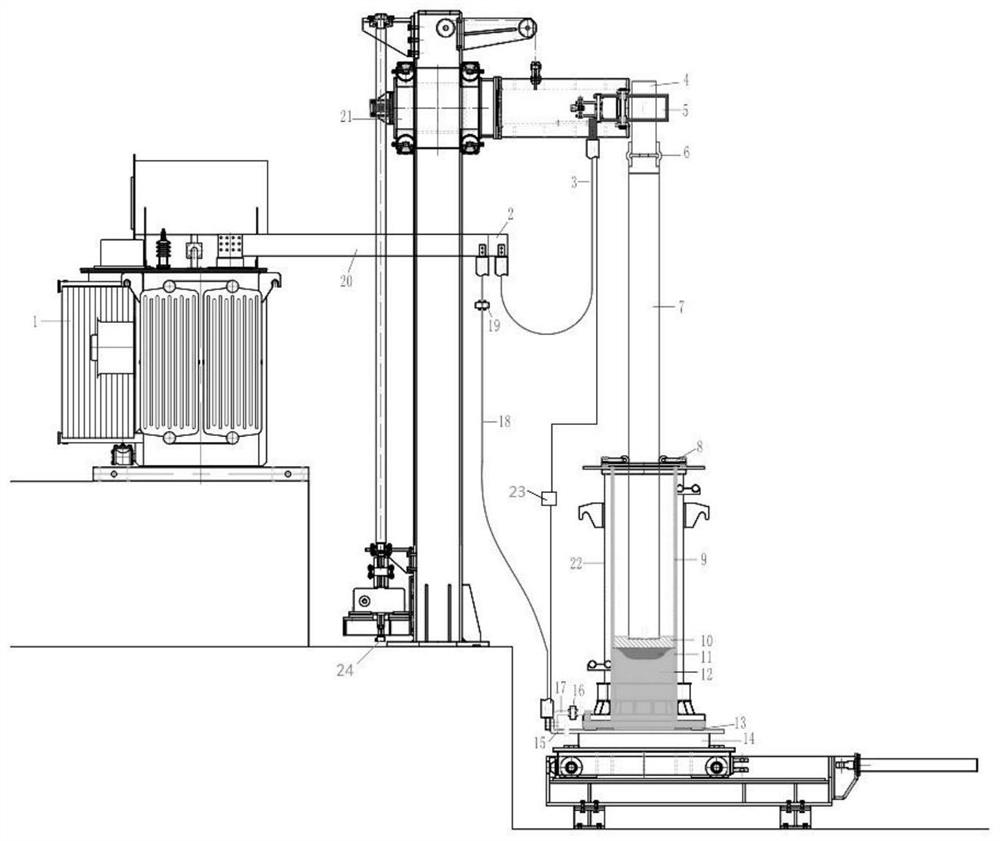
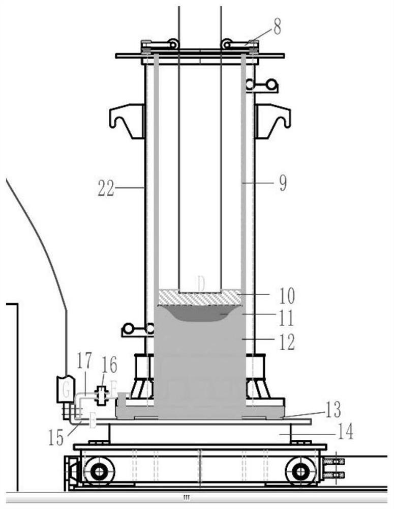
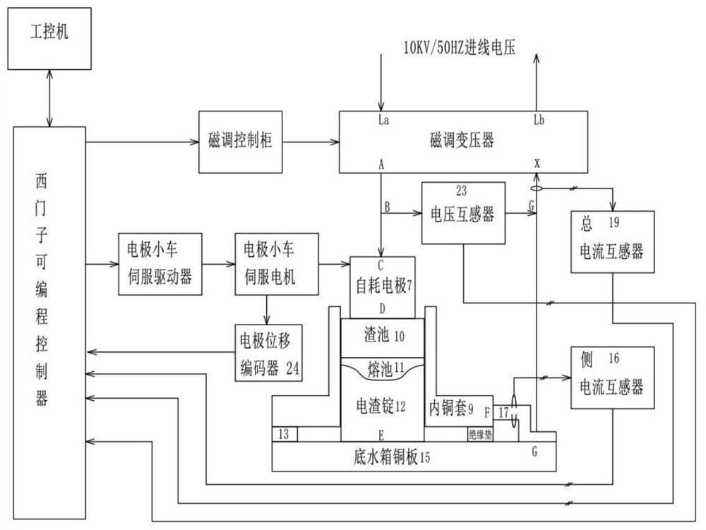
[0016] Such as Figure 1 to Figure 3 As shown, a conductive electroslag furnace with fixed crystallizer constant melting speed side flow control, including smelting transformer 1, transformer secondary side a-phase output copper bar 2, a-phase water-cooled cable 3, electrode dummy 4, copper electrodes Chuck 5, electrode flexible connection 6, electrode 7, insulating electrode centering frame 8, conductive fixed crystallizer 22, high temperature resistant insulating cushion 13, bottom water tank 14, bottom water tank copper plate 15, current transformer 16, side Current soft connection 17, x-phase water-cooled cable 18, total current transformer 19, transformer secondary side X-phase output copper bar 20, electrode lifting trolley 21, conductive fixed crystallizer 22, furnace mouth voltage transformer 23, electrode displacement Encoder 24.

[0017] The fixed mold 22 is designed as a conductive structure, and the conductive fixed mold 22 includes a mold copper inner sleeve 9 , ...


PUM


Abstract

The invention discloses a conductive type fixed crystallizer constant melting speed side flow control electroslag furnace and a constant melting speed control method. The furnace comprises a smelting transformer, a secondary side a-phase output copper bar, an a-phase water-cooled cable, an electrode false head, a copper electrode chuck, an electrode flexible connector, an electrode, an insulation type electrode centering frame, a conductive type fixed crystallizer, a high-temperature-resistant insulation cushion layer, a bottom water tank, a bottom water tank copper plate, a side current transformer, a side current flexible connector, an x-phase water-cooled cable, a total current transformer, a secondary side x-phase output copper bar, an electrode lifting trolley, a furnace mouth voltage transformer and an electrode displacement encoder. The method comprises the following steps: presetting an electrode voltage drop rate table of a furnace mouth voltage and an electrode length, automatically searching the table by a program, calculating a voltage drop on the length of an unmelted electrode, calculating a slag surface voltage of the electrode between a slag bath end and a crystallizer, dividing the slag surface voltage by a side current by the program to obtain a slag surface resistance value, taking the slag surface resistance value as a correction parameter of a melting speed control ring, and finely adjusting the descending speed of the electrode, so that large fluctuation of the insertion depth caused by unsatisfactory actual working conditions is compensated for.

Description

technical field [0001] The invention belongs to the technical field of special electroslag metallurgy, and in particular relates to an electroslag furnace with constant melting speed side flow control of a conductive fixed crystallizer and a constant melting speed control method. Background technique [0002] The constant melting rate control method of the current fixed mold type electroslag furnace has the advantages of stable thermal field of the slag pool, small shallow crystal segregation of the molten pool, and uniform composition of the electroslag ingot, and gradually eliminates the constant current and constant power of the old-fashioned electroslag furnace. control method. The existing constant melting rate control methods include the following two types: 1. Use the load cell to regularly sample the weight of the electrode or the weight of the bottom water tank, and use the electrode swing method to obtain the variation of the voltage and current at the furnace mout...

Claims


Application Information

Patent Timeline
Patent Type & Authority Applications(China)
IPC IPC(8): C22B9/18C22B9/187
CPCC22B9/18
Inventor 陈治锐仇云龙孙振平姜志军朱卫飞柳子平
Owner ZHONGXING ENERGY EQUIP
Learn More