
Low-torque spinning device

A low-torque, spinning-frame technology, used in spinning machines, continuous-winding spinning machines, textiles and papermaking, etc., to solve problems such as low spindle speed limits, poor yarn softness, and difficult production

Inactive Publication Date: 2021-05-07
HEBEI HONGRUN NEW FABRIC
View PDF6 Cites 0 Cited by
  • Summary
  • Abstract
  • Description
  • Claims
  • Application Information

AI Technical Summary

Problems solved by technology

However, when the twist is too low, the spinning breakage will increase sharply, causing difficulties in production
In order to solve this problem, textile enterprises generally add long-staple cotton to the spinning blend to increase the strength of the yarn, which will increase the cost of the product
Or, to solve the problem of spun yarn breakage, spinning companies generally reduce the spinning spindle speed to reduce the spinning tension. On the one hand, this method will sacrifice the output, on the other hand, there is a minimum limit on the spindle speed, and the effect is not particularly ideal.
[0004] Therefore, in order to achieve smooth spinning, the yarn needs a certain twist, and the greater the twist, the worse the softness of the yarn, but under the same cost and output, the yarn breakage will increase sharply when the twist is too low

Method used

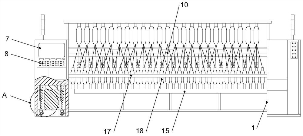
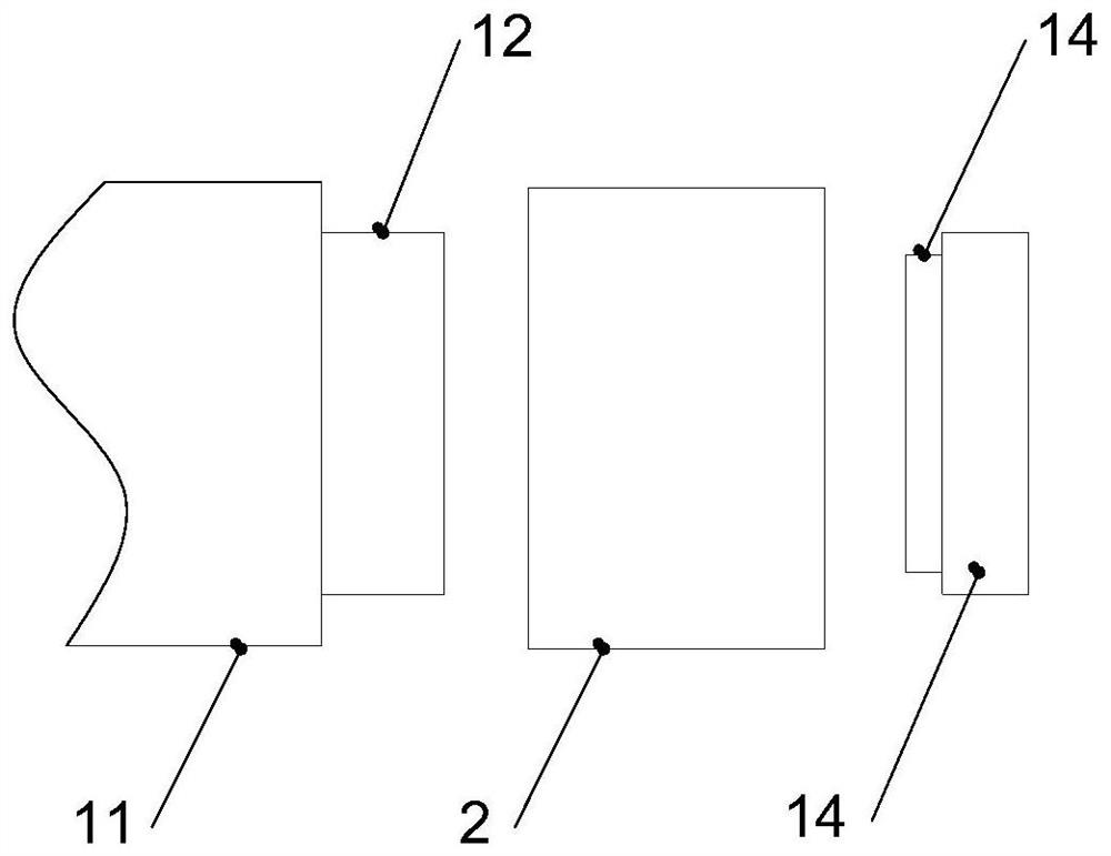

Image

  • Low-torque spinning device
  • Low-torque spinning device
  • Low-torque spinning device

Examples


Embodiment 1

[0030] like figure 1 and figure 2 Shown, a kind of low torque spinning device comprises spinning frame 1, and described spinning frame 1 comprises body 11, front roller 12, steel ring 13 and traveler 14, and described front roller 12 is fixedly connected with body 11, and described The steel ring 13 is fixedly connected to the body 11, and the traveler 14 is rotationally connected to the steel ring 13; the leaf plate 15, the leaf plate 15 is fixedly connected to the body 11; the gear motor 16, the gear motor 16 is fixedly connected to the body 11; the dragon belt 17, the dragon belt 17 is connected to the output end of the reduction motor 16; the single wheel 18, the single wheel 18 is connected to the body 11 in rotation, and the single wheel 18 is connected to the body through static friction Dragon belt 17 is connected, and the quantity of described single wheel 18 is multiple; Yarn 10, described yarn 10 is connected with single wheel 18 by static friction; False twisting...

Embodiment 2

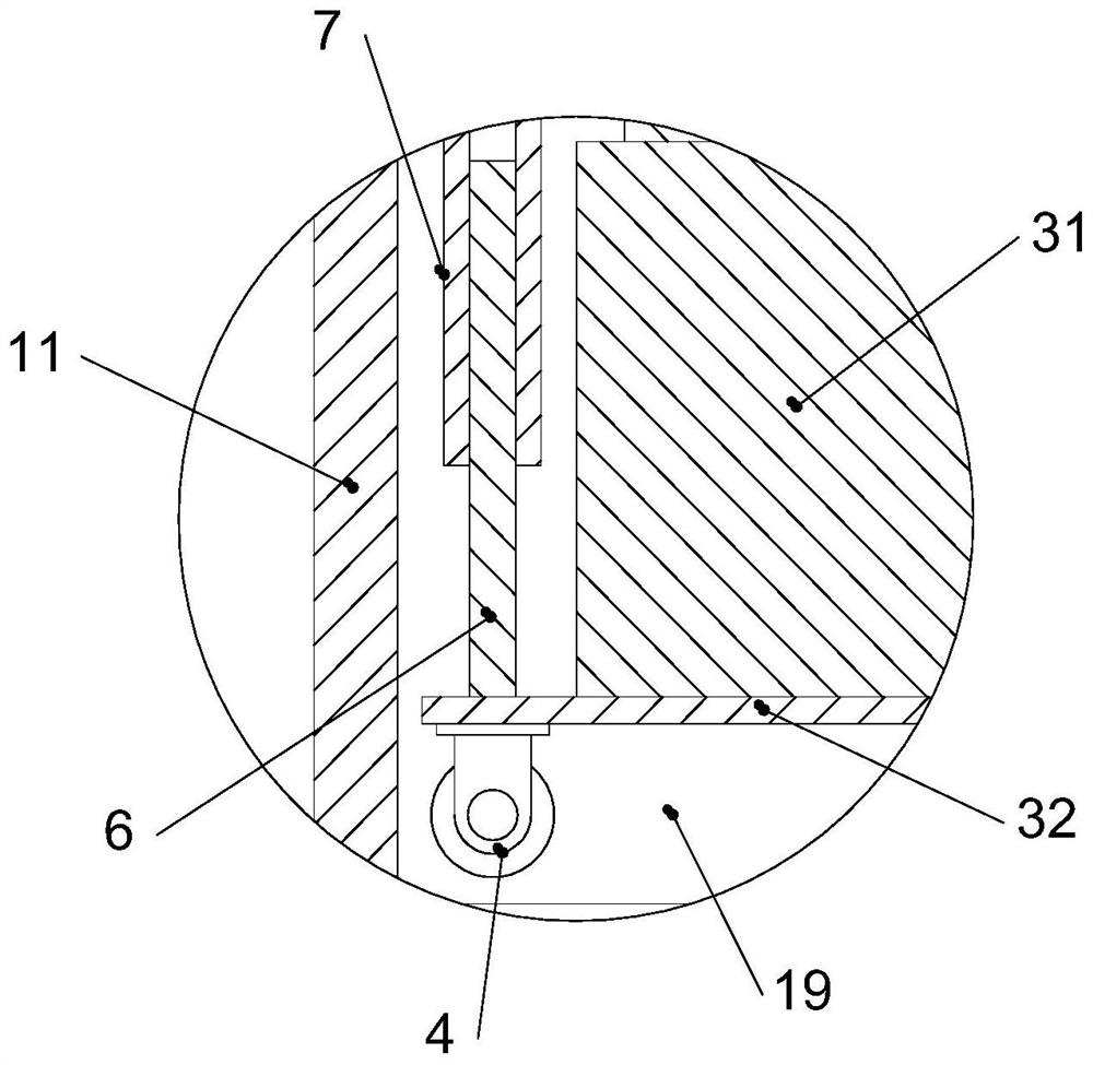
[0035] like image 3 As shown, the bottom of the body 11 is fixedly provided with an installation chamber 19, the installation chamber 19 is fixedly connected with a hydraulic lifting device 3, and the bottom of the hydraulic lifting device 3 is fixedly connected with a universal wheel with a self-locking function 4. The hydraulic lifting device 3 includes a hydraulic lifting column 31 and a mounting plate 32, the top of the hydraulic lifting column 31 is fixedly connected to the inner top surface of the installation chamber 19, and the mounting plate 32 is fixedly connected to the bottom of the hydraulic lifting column 31, The universal wheels 4 are fixedly connected to the four corners of the bottom surface of the hydraulic lifting column 31 by screws. In the present invention, the function of the hydraulic lifting device is as follows: ① the height of the body 11 can be adjusted by the hydraulic lifting device 3; ② after the universal wheel 4 is put down, the whole device ...

Embodiment 3

[0038] Embodiment 3: Improvement of adding a cluster in the drafting area

[0039] Spinning frame 1 is the main process to improve spinning quality and output, and process design, special parts configuration, and equipment operation status have a great influence on yarn quality. In order to improve the quality of the yarn 10, the present invention optimizes several aspects of the spun yarn collector, the type selection of the traveler 14, the design of the spindle speed, and the improvement of the drafting process.

[0040]In order to make up for the shortcoming of low final yarn strength caused by low spun yarn twist, the present invention installs a concentrator in the spun yarn process. The main function of the concentrator is to reduce the width of the fiber strands and arrange the floating fibers. The present invention is tested on a certain 18.2tex variety, and the spun yarn twist coefficient is designed to be 240. After the concentrator is installed, the yarn strength i...


PUM

PropertyMeasurementUnit
Lengthaaaaaaaaaa

Abstract

The invention discloses a low-torque spinning device. The low-torque spinning device comprises a spinning frame, a fender, a speed reducing motor, a tangential belt, a single wheel disc, yarns and false twisting equipment, wherein the spinning frame comprises a body, a front roller, a steel collar and a steel wire ring; the front roller is fixedly connected with the body; the steel collar is fixedly connected with the body; the steel wire ring is rotationally connected with the steel collar; the fender is fixedly connected with the body; the speed reducing motor is fixedly connected to a frame head of the body; the tangential belt is in transmission connection with the output end of the speed reducing motor; the single wheel disc is rotationally connected with the body and is connected with the tangential belt through static friction force; the yarns are connected with the single wheel disc through static friction force; and the false twisting equipment is arranged between the front roller and the steel collar. By means of the false twisting effect, the twisting degree and the strength of an original spinning section with the lowest twisting degree and the most prone to end breakage are greatly improved from a front roller jaw to a yarn guide hook, and therefore the end breakage of the spinning section is greatly reduced or even eliminated.

Description

technical field [0001] The invention relates to the field of spinning equipment, in particular to a low-torque spinning device. Background technique [0002] With the continuous improvement of people's living standards, users in the market have an increasing demand for the wearing comfort of pure cotton products, especially underwear, baby products, fashion clothing, high-end towels, etc. Product comfort, high-end, natural, leisure, personality, etc. have become important indicators to measure the quality of products. [0003] In order to make pure cotton products soft and comfortable, reducing yarn twist is the most effective method. However, when the twist is too low, the spinning ends will increase sharply, causing difficulties in production. In order to solve this problem, textile enterprises generally add long-staple cotton to the spinning blend to increase the strength of the yarn, which will increase the cost of the product. Or, to solve the problem of spun yarn br...

Claims


Application Information

Patent Timeline
IPC IPC(8): D01H1/11D01H1/243
CPCD01H1/11D01H1/243
Inventor 王瀚巍李春苗刘倩谷友庆
Owner HEBEI HONGRUN NEW FABRIC
Learn More