
Supporting device of attached lifting scaffold

A technology for lifting scaffolding and supporting devices, which is applied to the accessories of scaffolding, scaffolding supported by house structures, and house structure supports, etc. It can solve problems such as weak bearing capacity, deformation and damage, and unsatisfactory comprehensive mechanical properties of connections and lateral bending resistance.

Pending Publication Date: 2021-05-07
甘肃圣华源科技有限公司
View PDF0 Cites 0 Cited by
  • Summary
  • Abstract
  • Description
  • Claims
  • Application Information

AI Technical Summary

Problems solved by technology

[0002] The support devices in most of the attached lifting scaffolds currently used are not enough to resist up and down due to their structural reasons, for example, because the fastening position of the upper and lower bolt holes of the anti-drop assembly and the guide frame is located on the same vertical center line of the two During the operation, the excessive side bending and swing between the guide frame and the scaffold guide rail caused the guide frame to fall off and fail. The comprehensive mechanical properties of the connection and the ability to resist side bending are not ideal. Complicated, prone to deformation and damage during use, and prone to performance degradation due to dust adhesion

Method used


Image

  • Supporting device of attached lifting scaffold
  • Supporting device of attached lifting scaffold
  • Supporting device of attached lifting scaffold

Examples


Embodiment Construction

[0030] In order to make the object, technical solution and advantages of the present invention clearer, the present invention will be further described in detail below in conjunction with the accompanying drawings and embodiments. It should be understood that the specific embodiments described here are only used to explain the present invention, not to limit the present invention.

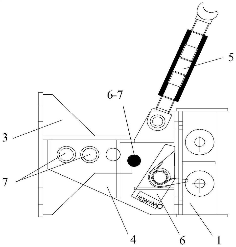
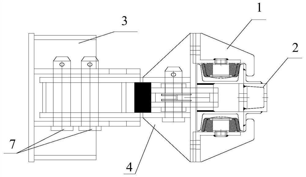
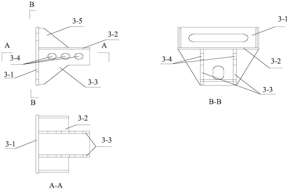
[0031] Such as Figure 1-7 As shown, among them, figure 1 It is a structural schematic diagram of the supporting device of the attached lifting scaffold of the present invention; figure 2 yes figure 1 The top view structure diagram after matching the guide rail; image 3 Schematic diagram of the structure of the support base in the support device of the present invention; Figure 4 It is a structural schematic diagram of the docking block in the support device of the present invention; Figure 5 is a schematic structural view of the guide frame of the present invention; Figure 6 It is a str...


PUM


Abstract

The invention discloses a supporting device of an attached type lifting scaffold. The supporting device comprises an anti-falling combination body and a supporting base fixed to a frame. The anti-falling combination body comprises a butt joint block, an unloading top support and an anti-falling stopping structure. The butt joint block is located between the supporting base and a guide rail, and the side, close to the supporting base, of the butt joint block is fixedly installed on the supporting base; the unloading top support is installed at the top end of the butt joint block in the vertical direction; and the butt joint block is close to the contact face of the guide rail, and a side plate right opposite to the contact face of the guide rail is a butt joint main plate which is provided with a pair of guide frames. The anti-falling stopping structure is installed on the butt joint main plate and on the side away from the guide rail direction, and excitation teeth of the anti-falling stopping structure penetrate through an opening in the butt joint main plate and stretch into a clamping opening in the contact face of the guide rail. The supporting device of an attached type lifting scaffold is of an open type structure, is compact in structure, convenient to install and disassemble, high in building environment adaptability, sensitive and accurate in anti-falling action and high in reliability.

Description

technical field [0001] The invention belongs to scaffold accessories, in particular to a supporting device for an attached lifting scaffold. Background technique [0002] The support devices in most of the attached lifting scaffolds currently used are not enough to resist up and down due to their structural reasons, for example, because the fastening position of the upper and lower bolt holes of the anti-drop assembly and the guide frame is located on the same vertical center line of the two During the operation, the excessive side bending and swing between the guide frame and the scaffold guide rail caused the guide frame to fall off and fail. The comprehensive mechanical properties of the connection and the ability to resist side bending are not ideal. Complicated, prone to deformation and damage during use, and prone to problems such as performance degradation due to dust adhesion. Contents of the invention [0003] The object of the present invention is to provide a s...

Claims


Application Information

Patent Timeline
IPC IPC(8): E04G3/28E04G5/00
CPCE04G3/28E04G5/00
Inventor 马德林包继德武世敏陈生林
Owner 甘肃圣华源科技有限公司
Learn More