Substrate glass light transmittance detection equipment and substrate glass preparation process

A technology for testing equipment and light transmittance, which is applied in transmittance measurement, measuring devices, and material analysis through optical means, and can solve problems such as difficult control of the detection path, uneven illumination at the imaging position, and inability to perform multi-angle detection. , to reduce the error and improve the control accuracy

Active Publication Date: 2021-05-07
茶陵晶辉电子实业有限公司
View PDF14 Cites 0 Cited by
  • Summary
  • Abstract
  • Description
  • Claims
  • Application Information

AI Technical Summary

Problems solved by technology

[0006] Aiming at the deficiencies of the prior art, the present invention provides a substrate glass light transmittance detection device, which has the advantages of being able to adjust multiple detection angles, accurate detection, and adjustable detection paths, and solves the problem of uneven illumination at the imaging position and difficult control Detection path, the problem that multi-angle detection cannot be performed

Method used


Image

  • Substrate glass light transmittance detection equipment and substrate glass preparation process
  • Substrate glass light transmittance detection equipment and substrate glass preparation process
  • Substrate glass light transmittance detection equipment and substrate glass preparation process

Examples


Embodiment Construction

[0037] The following will clearly and completely describe the technical solutions in the embodiments of the present invention with reference to the accompanying drawings in the embodiments of the present invention. Obviously, the described embodiments are only some, not all, embodiments of the present invention. Based on the embodiments of the present invention, all other embodiments obtained by persons of ordinary skill in the art without making creative efforts belong to the protection scope of the present invention.

[0038] As introduced in the background technology, there are deficiencies in the prior art. In order to solve the above technical problems, the present application proposes a substrate glass light transmittance detection device.

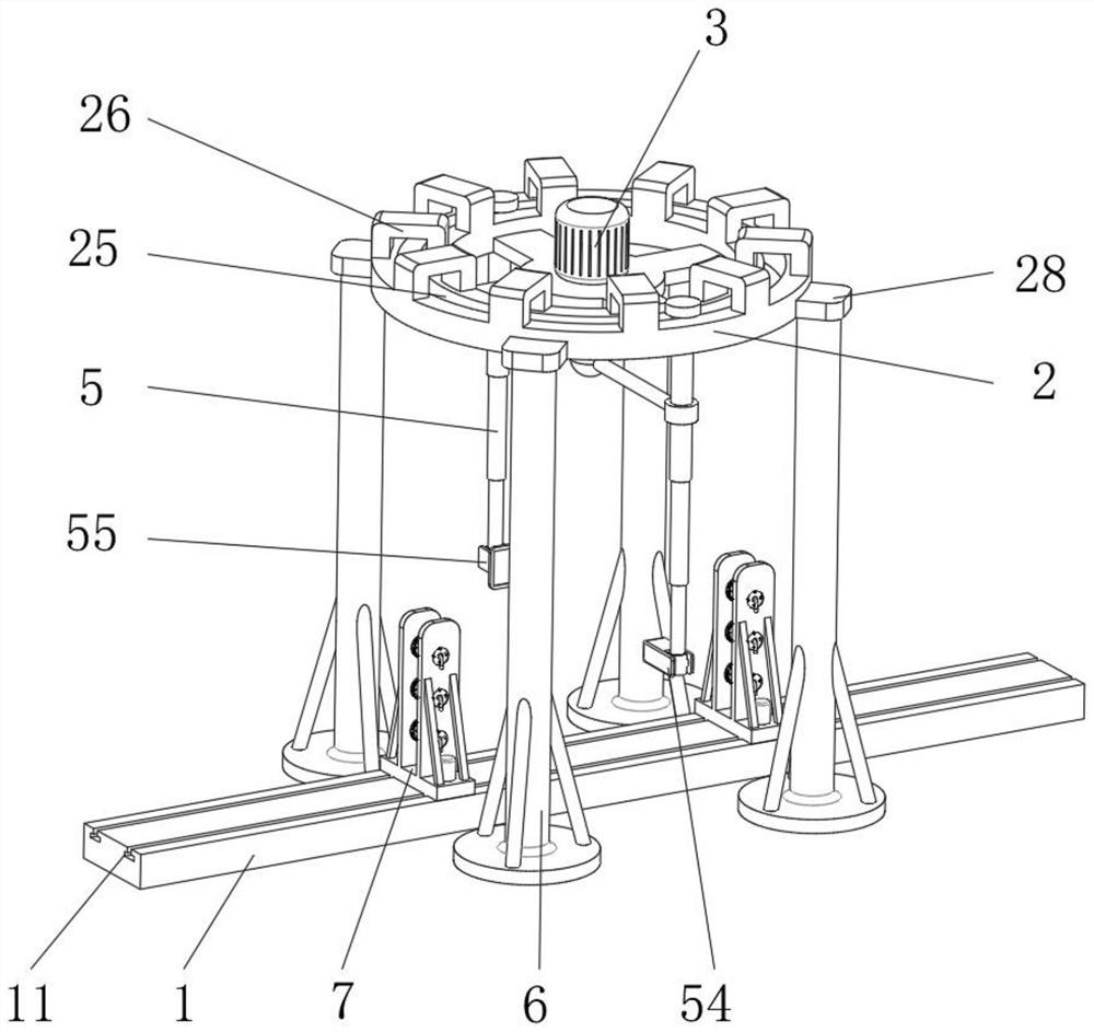
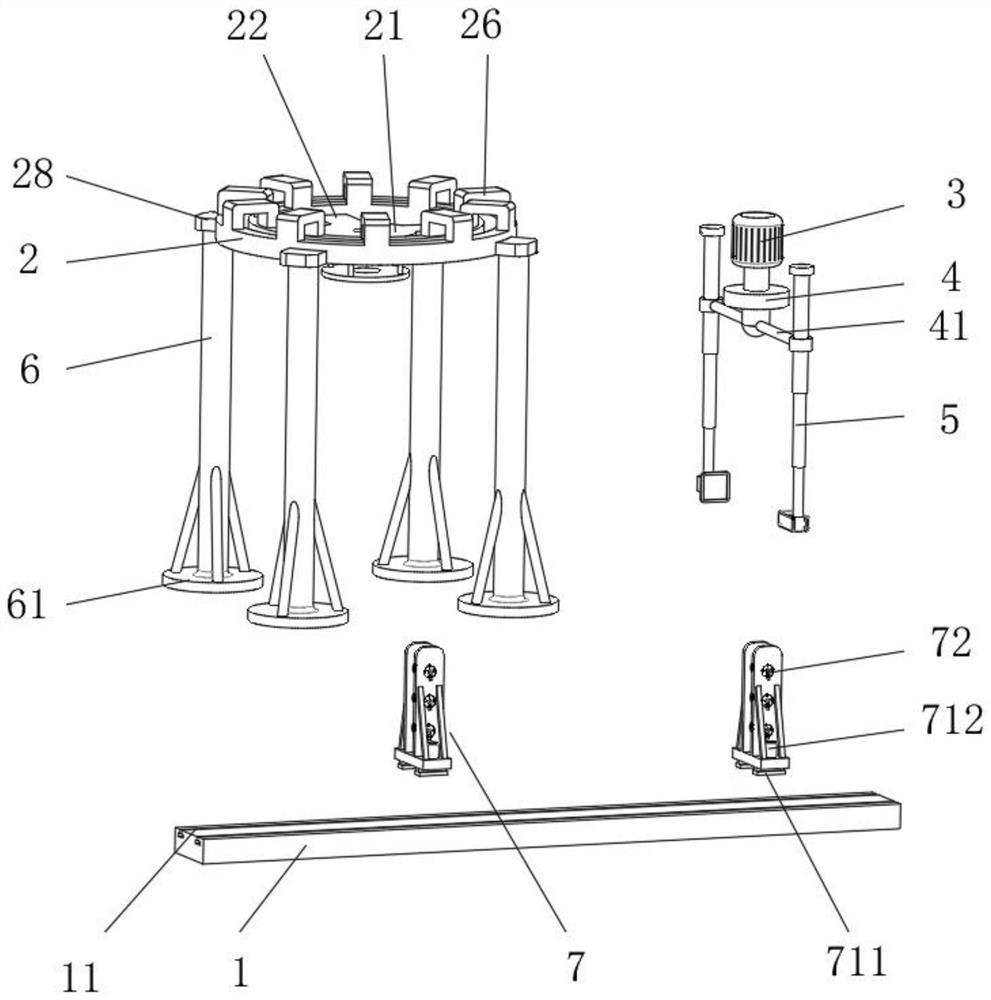
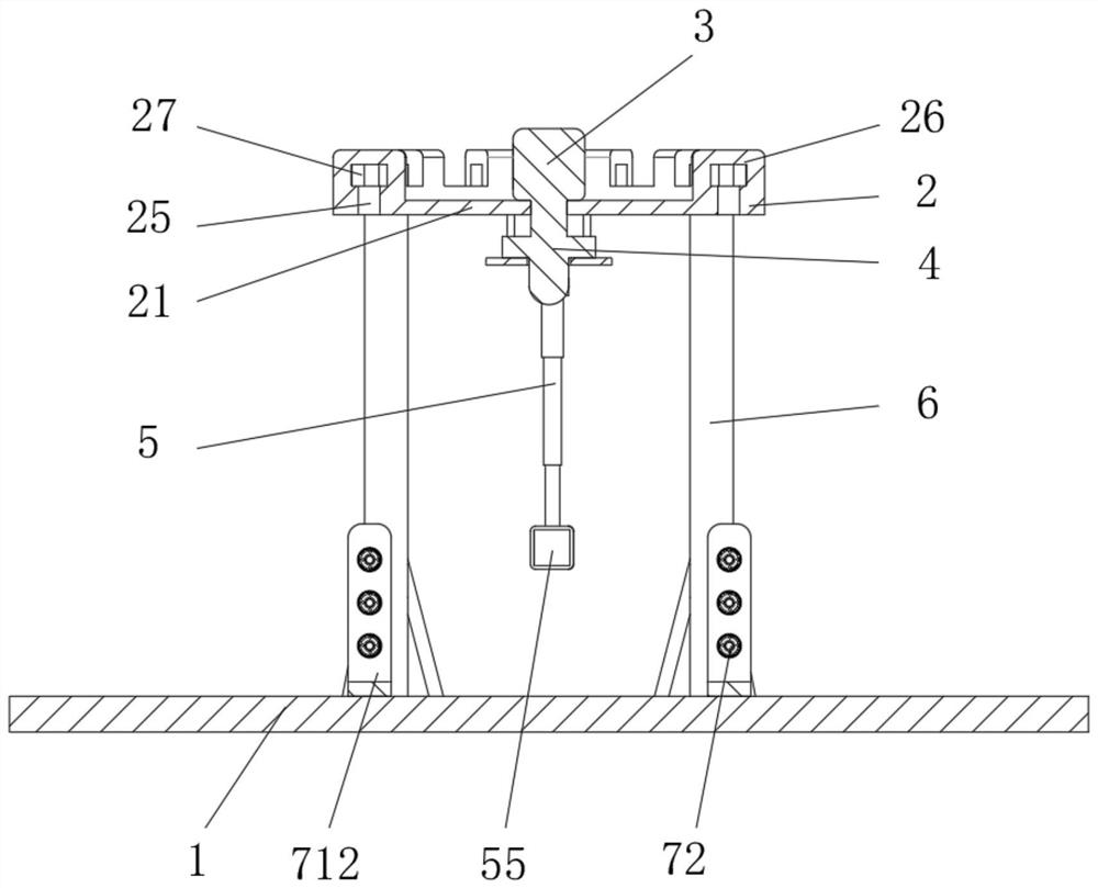
[0039] see Figure 1-11 , a substrate glass light transmittance detection equipment, including an electric slide 1, a differential 4, a hydraulic press 51, a light emitter 54, a light receiver 55 and an air compressor 73, and a detec...


PUM


Abstract

The invention relates to the technical field of liquid crystal panel production, and discloses substrate glass light transmittance detection equipment and a substrate glass preparation process. The substrate glass light transmittance detection equipment comprises an electric sliding rail, a differential mechanism, a hydraulic machine, a light emitter, a light receiver and an air compressor, a detection support is arranged above the electric sliding rail, and two telescopic lifting rods are arranged on the detection support in a lifting mode; hydraulic machines are arranged at the top ends of the telescopic lifting rods, detector mounting blocks are arranged at the bottom ends of the telescopic lifting rods, and a light emitter and a light receiver are arranged at the bottom ends of the two telescopic lifting rods correspondingly. The two telescopic lifting rods which are correspondingly arranged and can slide in the annular grooves are arranged, the two driving cross rods are driven by the driving shafts to synchronously rotate, the driving cross rods synchronously rotate and are transmitted to the two telescopic lifting rods through the connecting rings to enable the two telescopic lifting rods to synchronously rotate, and then the included angles between the two telescopic lifting rods and the glass substrate can be adjusted; and therefore, the light transmittance of different angles of each point in the same column position can be further detected.

Description

technical field [0001] The invention relates to the technical field of liquid crystal panel production, in particular to a substrate glass light transmittance detection device and a substrate glass preparation process. Background technique [0002] The glass substrate is a basic component that constitutes a liquid crystal display device. This is a thin glass sheet produced by the float process with an extremely flat surface. There are three main process technologies for producing glass substrates for flat panel displays, which are float method, orifice downdraw method and overflow fusion method. During a series of operations such as forming, cutting, grinding, and manipulating the glass substrate, foreign matter such as air bubbles, impurities, or stones may be mixed in due to various factors, which may cause stains, scratches, cuts, or cracks on the glass substrate. Multiple flaws. In addition, during the product manufacturing process, various processing will be performe...

Claims


Application Information

Patent Timeline
IPC IPC(8): G01N21/59G01N21/01
CPCG01N21/59G01N21/01
Inventor 张海东张海宁
Owner 茶陵晶辉电子实业有限公司
Why Eureka
Try Eureka