Double-end current ratio distance measurement method for rail transit traction in-phase power supply system

A technology of power supply system and rail transit, applied in the direction of information technology support system, measuring electricity, measuring devices, etc., can solve problems such as inaccurate calculation of fault location, zero current, and error in distance measurement results

Active Publication Date: 2021-05-07
TIANJIN KEYVIA ELECTRIC CO LTD +3
View PDF6 Cites 1 Cited by
  • Summary
  • Abstract
  • Description
  • Claims
  • Application Information

AI Technical Summary

Problems solved by technology

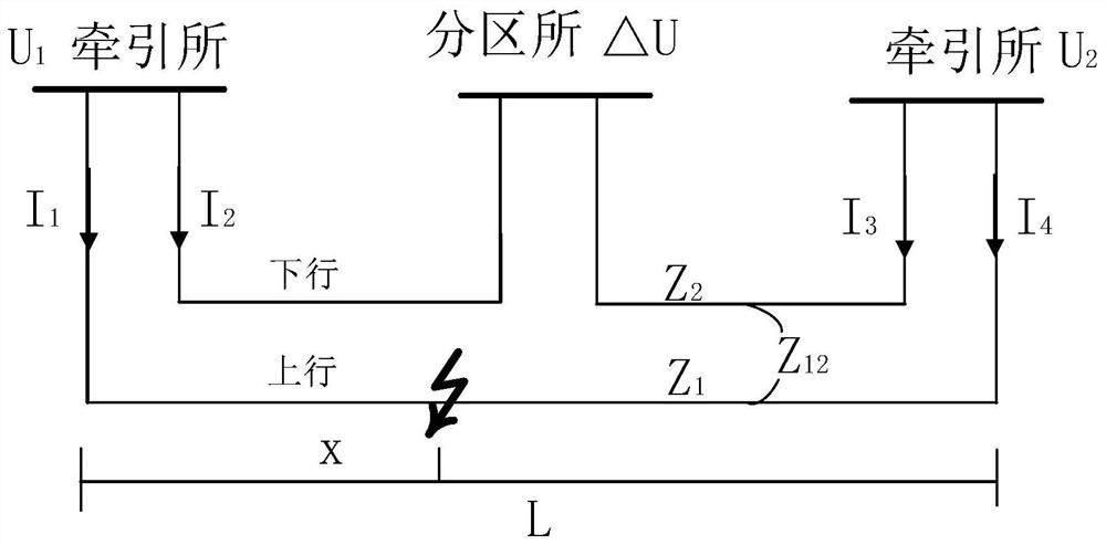
[0003] However, the adoption of the same-phase traction power supply system has brought new problems. The above-mentioned ranging method has the following defects: 1. For the through-type double-terminal or multi-terminal traction power supply system with the same phase, since the phases of each power supply are the same, if the catenary breaks down , because there is zero current in the non-fault side of the double-ended power supply mesh
At this time, only relying on the current on the fault side, the fault location cannot be accurately calculated by means of the uplink and downlink current ratio ranging method
Failure to quickly and accurately calculate the fault location is very detrimental to the railway system in operation; 2. When locating the fault location with the traditional ranging method, it is first necessary to determine the row where the fault location is located before it can be brought into the corresponding distance measurement The algorithm calculates the location of the fault. If the row of the fault is wrongly judged, the distance measurement result will also be wrong.

Method used


Image

  • Double-end current ratio distance measurement method for rail transit traction in-phase power supply system
  • Double-end current ratio distance measurement method for rail transit traction in-phase power supply system
  • Double-end current ratio distance measurement method for rail transit traction in-phase power supply system

Examples


Embodiment Construction

[0032] It should be noted that, in the case of no conflict, the embodiments of the present invention and the features in the embodiments can be combined with each other.

[0033] In describing the present invention, it should be understood that the terms "center", "longitudinal", "transverse", "upper", "lower", "front", "rear", "left", "right", " The orientations or positional relationships indicated by "vertical", "horizontal", "top", "bottom", "inner" and "outer" are based on the orientations or positional relationships shown in the drawings, and are only for the convenience of describing the present invention and Simplified descriptions, rather than indicating or implying that the device or element referred to must have a particular orientation, be constructed and operate in a particular orientation, and thus should not be construed as limiting the invention. In addition, the terms "first", "second", etc. are used for descriptive purposes only, and should not be interpreted...


PUM


Abstract

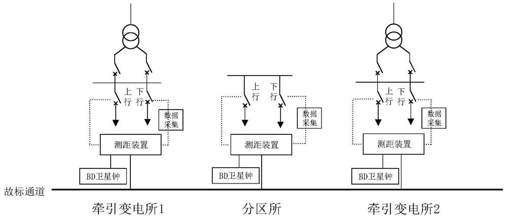
The invention provides a double-end current ratio distance measurement method for a rail transit traction in-phase power supply system, and the method comprises the following steps of: S1, in a traction power supply system adopting an in-phase power supply mode, respectively arranging a fault distance measurement device in each traction substation and each section post in the same power supply interval; and S2, connecting and communicating the fault distance measurement devices in the traction substations and the section posts through optical fibers so as to obtain electric quantity data of adjacent substations and realize real-time interaction of information. According to the double-end current ratio distance measurement method for the rail transit traction in-phase power supply system, the problem that accurate distance measurement cannot be achieved due to the fact that the non-fault side current is zero when a fault occurs is solved; the method is applied to various closed mesh loops in an operation line, the fault position can be quickly and accurately calculated by processing data on the two sides, and the requirements of a railway system in operation are met.

Description

technical field [0001] The invention belongs to the field of electrified railways, and in particular relates to a double-terminal current ratio ranging method for a rail transit traction in-phase power supply system. Background technique [0002] At present, my country's electrified railways use power frequency single-phase AC power supply. When the catenary of the traction power supply system fails, accurate and fast location of the fault point is the guarantee for the stable operation of the system. In the traditional multi-line power supply system with single-ended power supply in parallel, the uplink and downlink lines can be regarded as symmetrical, that is, the parameters are the same. In the closed mesh, the line voltage drop can be mapped to the line current. Since the line voltage drop is the same, the fault distance can be calculated through the relationship between the single-ended or segmented uplink and downlink current ratios or the uplink current ratio (AT pow...

Claims


Application Information

Patent Timeline
Patent Type & Authority Applications(China)
IPC IPC(8): G01R31/08
CPCG01R31/088Y04S10/52
Inventor 李汉卿闫兆辉陈敏林云志尹建斌姚楠王纯伟王颖赵双石魏应冬白青林宋金川李笑倩
Owner TIANJIN KEYVIA ELECTRIC CO LTD
Why Eureka
Try Eureka