Junction temperature estimation method of power device, power device, motor controller and computer readable storage medium

A technology of power devices and computers, applied in the field of motor controllers, computer-readable storage media, and power devices, can solve the problems of unable to measure the junction temperature of power device MOSFETs and unable to protect power device MOSFETs over temperature

Pending Publication Date: 2021-05-07
UNITED AUTOMOTIVE ELECTRONICS SYST
View PDF0 Cites 1 Cited by
  • Summary
  • Abstract
  • Description
  • Claims
  • Application Information

AI Technical Summary

Problems solved by technology

However, the temperature of these temperature sensors can only measure the case temperature at the bottom of the power device MOSFET (referred to as the case temperature), and cannot measure the junction temperature of the power device MOSFET, and thus cannot perform over-temperature protection on the power device MOSFET well and accurately.

Method used


Image

  • Junction temperature estimation method of power device, power device, motor controller and computer readable storage medium
  • Junction temperature estimation method of power device, power device, motor controller and computer readable storage medium
  • Junction temperature estimation method of power device, power device, motor controller and computer readable storage medium

Examples


Embodiment Construction

[0052] The specific embodiments of the present application will be further described in detail below in conjunction with the accompanying drawings.

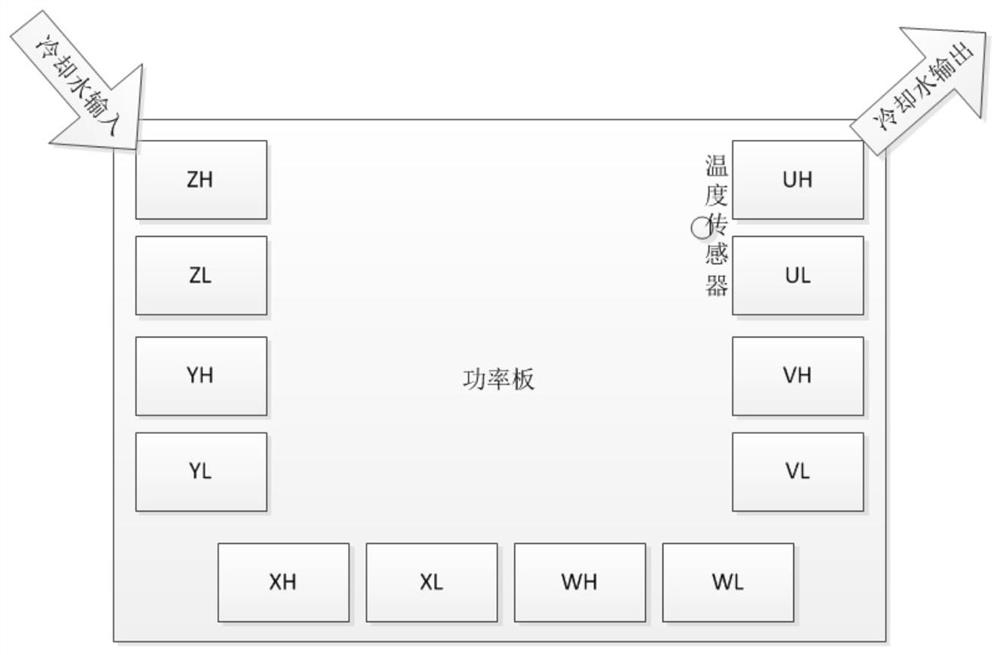
[0053] Such as figure 1 A schematic diagram showing a possible deployment of a power substrate. The 48V motor controller adopts such as figure 1 In the power substrate shown, there are 12 power device MOSFETs deployed in a "U" shape on the power substrate, which are ZH, ZL, YH, YL, XH, XL, WH, WL, VL, VH, UL as shown in the figure. and UH. One or more temperature sensors may also be disposed on the periphery of each power device, for example, a temperature sensor is disposed between UH and UL as shown.

[0054] In order to prevent over-temperature failure of devices on the power substrate, cooling water is usually introduced to cool down the power substrate. Specifically, the cooling water flows into the water channel below the power substrate from the upper left side of the figure, and flows through the 12 MOSFETs ZH→ZL→YH→Y...


PUM


Abstract

The embodiment of the invention discloses a junction temperature estimation method of a power device, the power device, a motor controller and a computer readable storage medium. The method comprises the steps: obtaining the switching loss and conduction loss of a first power device, carrying out loss calculation on the switching loss and the conduction loss to obtain the average loss of the first power device, and calculating the total temperature rise of the first power device according to the average loss of the first power device, and determining a temperature sensor adjacent to the first power device, calculating the water temperature of cooling water according to the temperature sensor, and performing junction temperature estimation on the total temperature rise of the first power device and the water temperature of the cooling water to obtain the junction temperature of the first power device. By implementing the application, the junction temperature of the power device MOSFET can be accurately estimated, and then over-temperature protection is performed on the power device MOSFET according to the junction temperature.

Description

technical field [0001] The present application relates to the technical field of semiconductors, and in particular to a junction temperature estimation method of a power device, a power device, a motor controller, and a computer-readable storage medium. Background technique [0002] In low-voltage electric drive products, 48V motor controllers cannot use insulated gate bipolar transistors (Insulated Gate Bipolar Transistor, IGBT) in high-voltage products as power devices, and instead use metal-oxide-semiconductor field-effect transistors (Metal-Oxide- Semiconductor Field-Effect Transistor, MOSFET), to achieve a good cost reduction effect simultaneously. Unlike high-voltage motor controllers that use ceramic copper-clad laminates (Direct Bonding Copper, DBC) as power substrates, 48V motor controllers generally choose thick copper printed circuit boards (Printed Circuit Board, PCB) as power substrates, and paste Power device MOSFET. Compared with the traditional power device...

Claims


Application Information

Patent Timeline
Patent Type & Authority Applications(China)
IPC IPC(8): G06F30/20
CPCG06F30/20G06F2119/08
Inventor 王宇韩浩黄立勇黄宜坤
Owner UNITED AUTOMOTIVE ELECTRONICS SYST
Why Eureka
Try Eureka