Supercharge Your Innovation With Domain-Expert AI Agents!

Method for manufacturing joined body

A manufacturing method and joint body technology, which are applied in the direction of manufacturing tools, rod connections, and connecting members, etc., can solve problems such as the generation of oxide layers.

Active Publication Date: 2021-05-07
KYB CORP
View PDF10 Cites 0 Cited by
  • Summary
  • Abstract
  • Description
  • Claims
  • Application Information

AI Technical Summary

Problems solved by technology

However, when the gap between the circular protrusion and the circular hole is increased, the surface area where the material (burr) flowing into the gap comes into contact with the air increases, and along with this, an oxide layer tends to be generated inside the circular hole.

Method used


Image

  • Method for manufacturing joined body
  • Method for manufacturing joined body
  • Method for manufacturing joined body

Examples


Embodiment Construction

[0019] Hereinafter, embodiments of the present invention will be described with reference to the drawings.

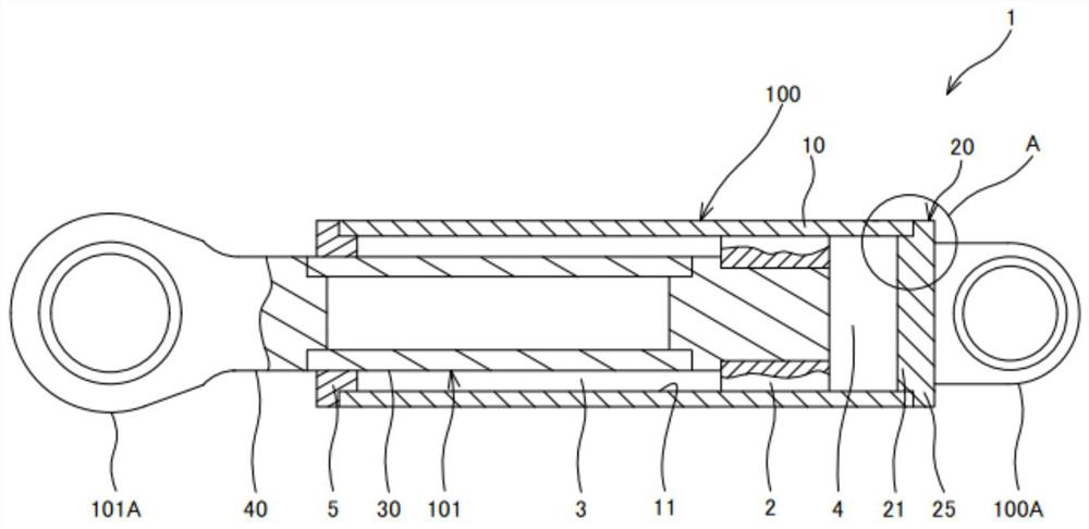
[0020] Hereinafter, a case where the joined body is the cylinder tube 100 of the hydraulic cylinder (fluid pressure cylinder) 1 will be described.

[0021] First, refer to figure 1 , the overall structure of the hydraulic cylinder 1 including the cylinder tube 100 as a joined body will be described.

[0022] The hydraulic cylinder 1 is an actuator that operates telescopically by the hydraulic pressure of working oil (working fluid) in a rod-side chamber 3 and an opposite-rod-side chamber 4 that are two cylinder chambers.

[0023] Such as figure 1 As shown, the hydraulic cylinder 1 has: a cylindrical cylinder tube 100; a piston rod 101, which is inserted into the cylinder tube 100; sliding on the inner surface.

[0024] The cylinder pipe 100 is provided with a cylindrical cylinder head 5 which seals an opening at one end (tip end) and supports a piston rod 101 in a s...


PUM


Abstract

A method for manufacturing a cylinder tube includes a joining step in which an end surface (15) of a tube main body (10) and a flange portion (25) are abutted against each other and joined by friction pressure welding while in a state in which a through-hole (11) of the tube main body (10) and a protruding part (21) of a head member (20) are fitted to each other across a prescribed fitting clearance (FC) therebetween. The tube main body (10) has an inclined inner circumferential surface (13) the inner diameter of which decreases with distance from the end surface (15) along a rotation axis (O). In the joining step a fluid material plastically flowing from the end surface (15) of a first member and the flange portion (25) of a second member fills the fitting clearance (FC) from the base side of the protruding part (21) until the distal end of the fluid material is positioned inside the range of the inclined inner circumferential surface (13) in the rotation axis (O) direction. By means of the fluid material a noncontact portion (26b) and the first member are joined, and the inclined inner circumferential surface (13) and an outer peripheral surface of the protruding part (21) are joined.

Description

technical field [0001] The present invention relates to a method for producing a bonded body. Background technique [0002] Japanese Patent Application Laid-Open JP2008-12573A discloses a frictional joining method in which one member is rotated about a rotating shaft while pressing against the other member in parallel with the rotating shaft to engage, and, In this frictional engagement method, a circular protrusion protruding toward the other member coaxially with the rotation shaft is formed on one member, and a circular hole into which the circular protrusion is inserted is formed on the other member. [0003] In the frictional joining method disclosed in Japanese Patent Application Laid-Open JP2008-12573A, for example, the circular protrusion may be eccentric with respect to the rotating shaft due to the influence of machining accuracy. In this case, when one member is to be rotated to be engaged with the other member, the outer circumference of the circular protrusion ...

Claims


Application Information

Patent Timeline
Patent Type & Authority Applications(China)
IPC IPC(8): B23K20/12F15B15/14
CPCB23K20/12F15B15/1438F15B15/1457F15B15/1447F15B15/1423F16B7/00B23K2101/06
Inventor 永井康行
Owner KYB CORP
Features
  • R&D
  • Intellectual Property
  • Life Sciences
  • Materials
  • Tech Scout
  • Unparalleled Data Quality
  • Higher Quality Content
  • 60% Fewer Hallucinations
Learn More