Epoxy resin recovery system

A recovery system and epoxy resin technology, applied in chemical instruments and methods, cleaning methods and utensils, cleaning methods using liquids, etc., can solve problems such as affecting contact, troublesome handling, and epoxy resin cannot be recycled

Inactive Publication Date: 2021-05-11
王传坤
View PDF0 Cites 0 Cited by
  • Summary
  • Abstract
  • Description
  • Claims
  • Application Information

AI Technical Summary

Problems solved by technology

[0004] Aiming at the problems in the prior art, the present invention provides an epoxy resin recycling system, which solves the problem that when people recycle the epoxy resin on the surface of electronic components, most of the electronic components with epoxy resin are placed in the processing agent. In the process, use a treatment agent to dissolve the epoxy resin on the electronic components. If too many electronic components are processed at one time, the electronic components will pile up together. During the dissolution process, a lot of epoxy resin still stays inside the piled up electronic components. It is more troublesome, and the dissolved epoxy resin will stick to the surface of other electronic components, affecting the contact between the epoxy resin and the treatment agent on the surface of the electronic component, reducing the dissolution rate, and there will be a part of the dissolved epoxy resin during unloading. The epoxy resin remains inside the stacked electronic components, which will cause the problem that part of the epoxy resin cannot be recycled

Method used


Image

  • Epoxy resin recovery system
  • Epoxy resin recovery system
  • Epoxy resin recovery system

Examples


Embodiment Construction

[0026] In order to make the technical means, creative features, goals and effects achieved by the present invention easy to understand, the present invention will be further described below in conjunction with specific embodiments.

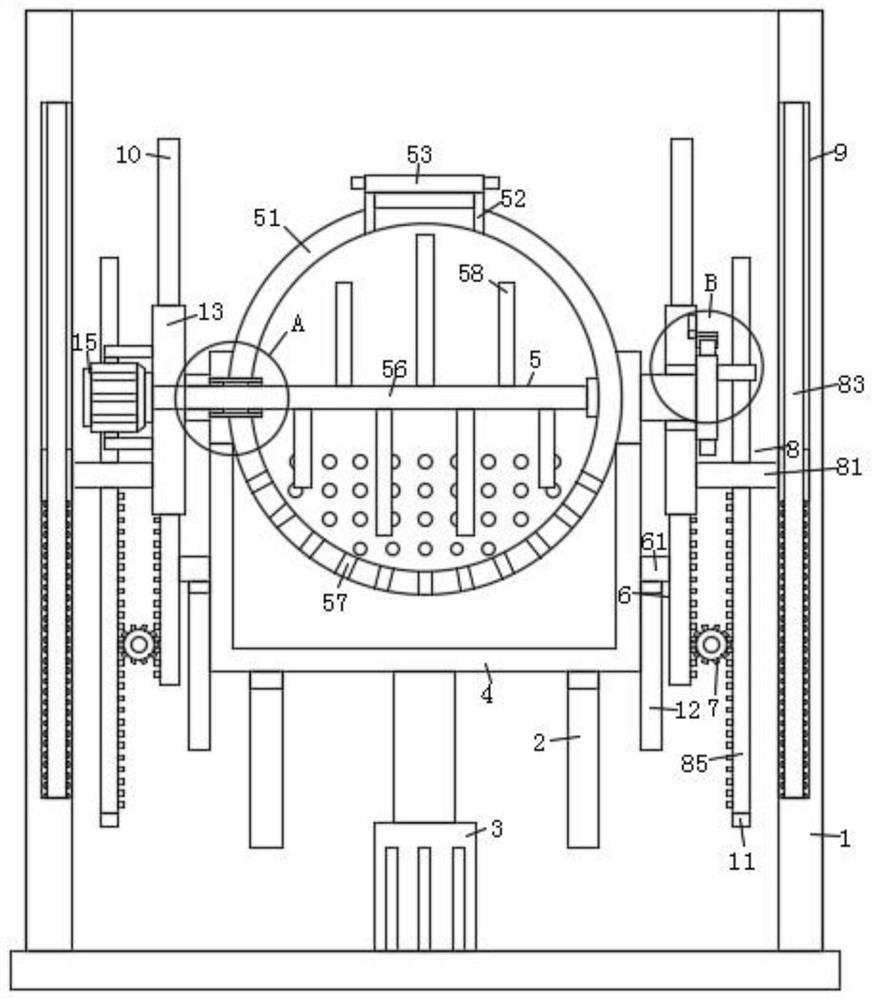
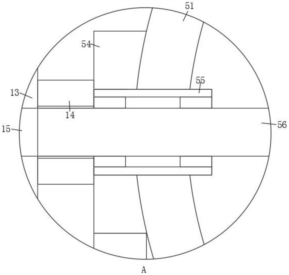
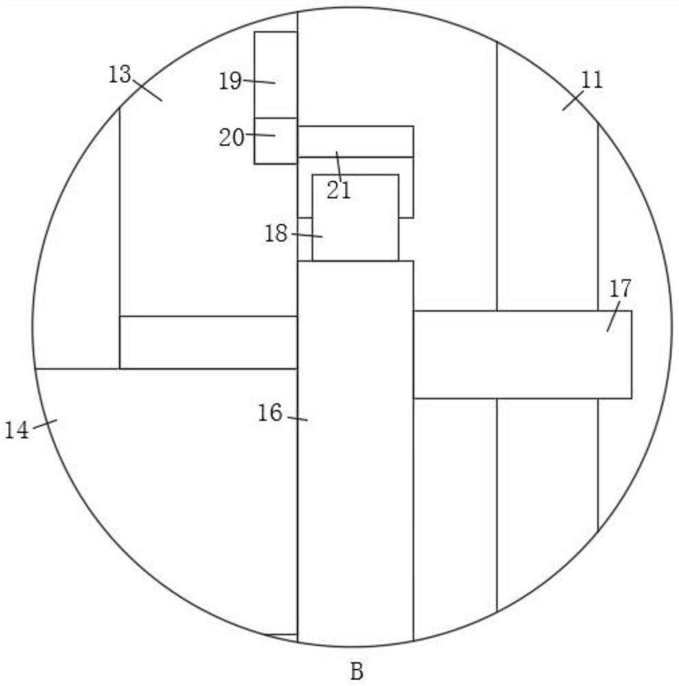
[0027] Such as Figure 1-Figure 7As shown, a kind of epoxy resin recycling system described in the present invention comprises housing 1, and the inner wall of both sides of described housing 1 is provided with limit groove 9, and the middle part of described housing 1 back inner wall is vertically provided with Two first fixing grooves 2, the two sides of the inner wall of the back of the housing 1 are provided with a second fixing groove 10, and the inside of the second fixing groove 10 is slidably connected with a mounting plate 13, and the mounting plate 13 is in phase with each other. A fixed rod 14 is rotatably connected to one side, and a storage mechanism 5 is installed between the fixed rods 14. The fixed rod 14 on one side of the housing...


PUM


Abstract

The invention relates to the field of processing equipment, in particular to an epoxy resin recovery system. The system comprises a shell, wherein limiting grooves are formed in the inner walls of the two sides of the shell correspondingly, two first fixing grooves are vertically formed in the middle of the inner wall of the back face of the shell, second fixing grooves are formed in the two sides of the inner wall of the back face of the shell correspondingly, mounting plates are slidably connected to the interiors of the second fixing grooves correspondingly, fixing rods are rotatably connected to the sides, close to each other, of the mounting plates correspondingly, a storage mechanism is jointly mounted between the fixing rods, and the fixing rod on one side of the interior of the shell penetrate through and is fixedly connected to the corresponding mounting plate by means of a bearing. According to the system, the storage mechanism with a stirring function is arranged on the two mounting plates, a rotating rod of the storage mechanism is connected with a servo motor, during work, the servo motor is used for rotating the rotating rod, the rotary rotating rods can stir electronic elements in a fixing shell by means of stirring plates, the stacked electronic elements are scattered, and dissolved epoxy resin can be prevented from staying in the stacked electronic components.

Description

technical field [0001] The invention relates to the field of processing equipment, in particular to an epoxy resin recycling system. Background technique [0002] Epoxy resin is the polycondensation product of epichlorohydrin and bisphenol A or polyol. Epoxy resin is used in the production of electronic components, and is usually wrapped on the outside of electronic components to achieve the purpose of insulating electronic components. [0003] At present, when people recycle the epoxy resin on the surface of electronic components, most of them put the electronic components with epoxy resin in the treatment agent, and use the treatment agent to dissolve the epoxy resin on the electronic components. If there are too many electronic components at one time , the electronic components will pile up together, and during the dissolution process, a lot of epoxy resin still stays inside the piled up electronic components, which is troublesome to handle, and the dissolved epoxy resin ...

Claims


Application Information

Patent Timeline
IPC IPC(8): B08B3/04B08B3/08B08B3/10B08B13/00
CPCB08B3/047B08B3/08B08B3/102B08B13/00B08B2220/04
Inventor 王传坤李飞红
Owner 王传坤
Why Eureka
Try Eureka