Main shaft capable of blocking nozzle and working method

A spindle and nozzle technology, applied in the direction of manufacturing tools, metal processing equipment, metal processing machinery parts, etc., can solve the problems of large oil damping volume, low speed, insufficient lubrication of magnetic damping bearings, etc., and achieve the effect of quick disassembly

Active Publication Date: 2021-05-11
苏州硕蓝智能科技有限公司
View PDF7 Cites 0 Cited by
  • Summary
  • Abstract
  • Description
  • Claims
  • Application Information

AI Technical Summary

Problems solved by technology

[0003] Among them, although the scavenger high-pressure cleaning nozzle solves the problems of large oil damping volume, low rotation speed and insufficient lubrication of the magnetic damping bearing in the prior art, but in the process of use, because the nozzle is always in the open state, when the nozzle is not When working, the debris generated during the processing will recoil into the nozzle and block the nozzle

Method used


Image

  • Main shaft capable of blocking nozzle and working method
  • Main shaft capable of blocking nozzle and working method
  • Main shaft capable of blocking nozzle and working method

Examples


Embodiment 1

[0041] During the rotation of the main shaft in the prior art, since the nozzle is always open, when the nozzle is not working, the debris generated during the processing will recoil into the nozzle to block the nozzle, so it is necessary to design a valve that can block the nozzle. The main shaft of the nozzle, the specific structure is as follows:

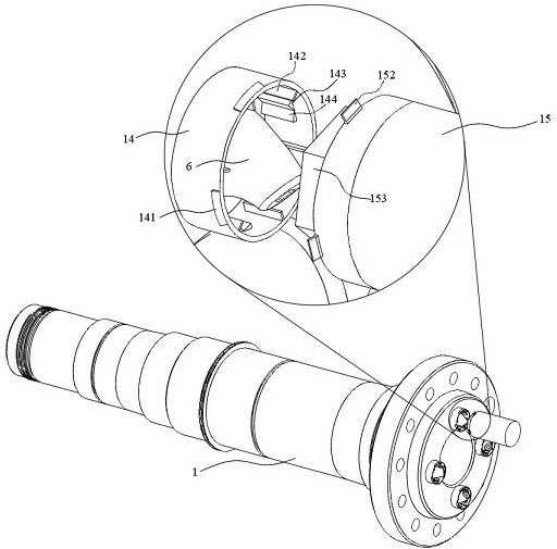
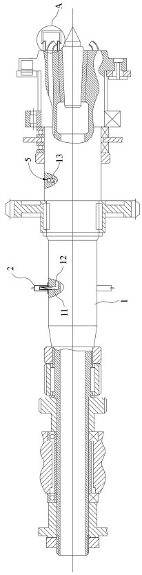
[0042] Main shaft body 1, the main shaft body 1 is a hollow structure, which has the following advantages: 1. The hollow main shaft body 1 is light in weight; 2. The hollow main shaft body 1 has high strength and is not easily deformed; 3. The hollow main shaft body 1 can reduce The driving force of the motor; a liquid injection groove 11 is opened in the middle of the main shaft body 1, and the liquid injection groove 11 extends radially from the outer wall of the main shaft body 1, so as to provide convenience for injecting cooling liquid into the main shaft body 1, correspondingly Compared with the method of feeding the coolan...

Embodiment 2

[0068] On the basis of the first embodiment, the second embodiment also provides a working method for the main shaft that can block the spout,

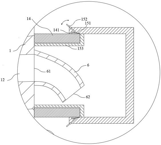
[0069] When the machine tool is adjusted to the cleaning state, the main shaft body 1 rotates at a high speed, and the cover body 15 is covered on the base 14 to block the nozzle 6, and the filter screen 24 is pushed by the right support plate 42 to shake off impurities, so that the cleaning brush 821 will Impurities are pushed into the blowdown box 81;

[0070] When the machine tool is adjusted to the working state, the main shaft body 1 rotates at a low speed, and the flow velocity of the coolant is increased by the left support plate 32 and the right support plate 42 moving closer to each other, and the vortex is formed through the stirring tank 13 to neutralize the coolant in each guide channel 12 ;

[0071] When the machine tool is adjusted to the pause state, the main shaft body 1 stops rotating, the cover body 15 is covered on...


PUM


Abstract

The invention relates to the field of machining, in particular to a main shaft capable of blocking a nozzle and a working method. The main shaft capable of blocking the nozzle comprises a main shaft body, a plurality of spraying heads, a plurality of bases and a plurality of cover bodies, wherein a plurality of limiting blocks are fixed on the outer side walls of the bases, and the thicknesses of the limiting blocks are gradually increased in the direction close to the main shaft body; the cover bodies can cover the bases to block the spraying heads, limiting grooves matched with the limiting blocks are formed in the inner side walls of the cover bodies, a plurality of poking blocks are hinged to the outer side walls of the cover bodies, and the poking blocks extend into the corresponding limiting grooves; and when the cover bodies are closed, the limiting blocks can be clamped into the limiting grooves, and the poking blocks are pushed to rotate anticlockwise. When cooling liquid is introduced into the spraying heads, the poking blocks are poked clockwise, so that the poking blocks push the limiting blocks to be disengaged from the limiting grooves, the situation that splashed chippings are back flushed into the spraying heads to block the spraying heads in the workpiece machining process is avoided, it is guaranteed that the spraying heads can be unblocked in the using process, and the cover bodies can be rapidly disassembled through the arrangement of the poking blocks.

Description

technical field [0001] The invention relates to the field of machining, in particular to a main shaft capable of blocking a spout and a working method. Background technique [0002] Chinese patent, the application number is CN202020340697.8, the application date is 2020.03.18, the publication number is CN211914231U, and the authorized announcement date is 2020.11.13. It provides a high-pressure cleaning nozzle of a scavenger, which belongs to the surface removal or cleaning technology using high-pressure water field. To solve the problems of large oil damping volume, low speed and insufficient lubrication of magnetic damping bearings in the prior art, the technical solution adopted: includes a shell, a coupling body, a small sealing rod, a spray head, a rotating spindle, and a nozzle. The shell is The shape of a hollow cylinder, the nozzle extends into the housing, and is set on the bottom of the rotating main shaft, the rotating main shaft is provided with a pipeline, the ...

Claims


Application Information

Patent Timeline
Patent Type & Authority Applications(China)
IPC IPC(8): B23Q11/00B23Q11/10
CPCB23Q11/10B23Q11/0042
Inventor 王勇
Owner 苏州硕蓝智能科技有限公司
Why Eureka
Try Eureka