Automobile brake-by-wire system and brake control method and device

A brake-by-wire and braking control technology, applied in the automotive field, can solve the problems of poor braking stability and slow braking response speed, and achieve the effect of high braking stability and fast braking response speed.

Pending Publication Date: 2021-05-11
BYD CO LTD
View PDF6 Cites 1 Cited by
  • Summary
  • Abstract
  • Description
  • Claims
  • Application Information

AI Technical Summary

Problems solved by technology

[0003] When the pressure generating device of the existing vehicle braking system cannot build pressure, emergency braking can only be performed through the braking pressure generated by the master cylinder. Slow speed and poor braking stability

Method used


Image

  • Automobile brake-by-wire system and brake control method and device
  • Automobile brake-by-wire system and brake control method and device
  • Automobile brake-by-wire system and brake control method and device

Examples


Embodiment 1

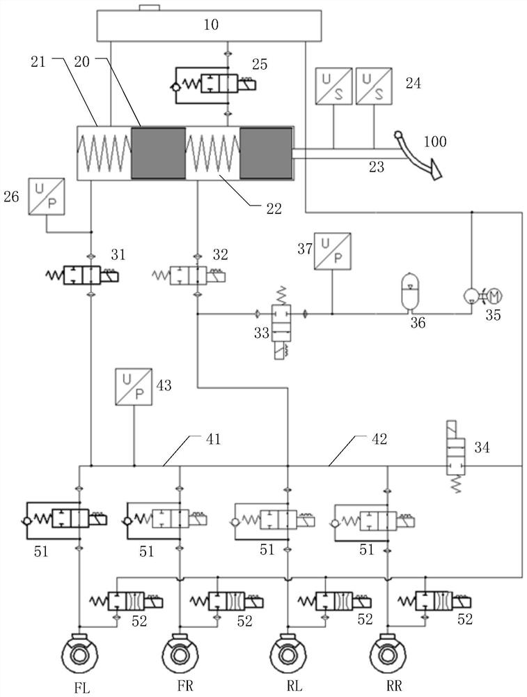
[0043] figure 1 It is a schematic diagram of an automobile brake-by-wire system according to an embodiment of the present application.

[0044] refer to figure 1 As shown, the brake-by-wire system provided in this embodiment includes a liquid storage pot 10, a master cylinder 20, a displacement sensor 24, a first normally open isolation valve 31, a second normally open isolation valve 32, a linear boost valve 33, an energy storage device 36 , pressure generating device 35 , front main wheel cylinder 41 , rear main wheel cylinder 42 and linear pressure reducing valve 34 .

[0045] The liquid storage pot is used to store brake fluid, which is the working medium of the brake system and used to transmit pressure, feedback torque, etc. The liquid storage pot is provided with a plurality of liquid inlets and liquid outlets for completing the circulation of the brake fluid in the system.

[0046] The master cylinder 20 includes a chamber 21 and a chamber 22. The master cylinder 20...

Embodiment 2

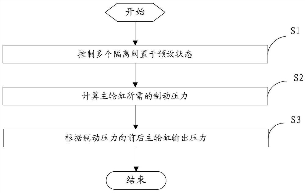
[0064] image 3 It is a flow chart of a braking control method according to an embodiment of the present application.

[0065] Such as image 3 As shown, the brake control method provided in this embodiment is applied to the brake-by-wire brake system provided in the previous embodiment, and the brake control method includes the following steps:

[0066] S1. Controlling multiple isolation valves to be in a preset state.

[0067] That is, when the car is normally powered on and started, the first normally open isolation valve and the second normally open isolation valve are controlled to close, and the front and rear isolation valves are controlled to be turned on. In this way, the pressure generated by the pressure generating device can enter the corresponding main wheel cylinder through the accumulator, and finally enter the supporting wheel cylinder to realize braking.

[0068] S2. Calculating the braking pressure required by the main wheel cylinder.

[0069] That is, th...

Embodiment 3

[0077] Figure 5 It is a block diagram of a braking control device according to an embodiment of the present application.

[0078] Such as Figure 5 As shown, the brake control device provided in this embodiment is applied to the brake-by-wire brake system provided in Embodiment 1, and the brake control device includes a brake control module 101 and a pressure calculation module 102 .

[0079] The brake control module 101 is used to control a plurality of isolation valves to be in a preset state.

[0080] That is, when the car is normally powered on and started, the first normally open isolation valve and the second normally open isolation valve are controlled to close, and the front and rear isolation valves are controlled to be turned on. In this way, the pressure generated by the pressure generating device can enter the corresponding main wheel cylinder through the accumulator, and finally enter the supporting wheel cylinder to realize braking.

[0081] The pressure calc...


PUM


Abstract

The invention provides an automobile brake-by-wire system and a brake control method and device. The system specifically comprises a liquid storage pot, a main cylinder, a displacement sensor, a first normally-open isolating valve, a second normally-open isolating valve, a linear pressure increasing valve, an energy accumulator, a pressure generating device, a front main wheel cylinder, a rear main wheel cylinder and a linear pressure reducing valve; and connection is carried out according to a mode specified by the technical scheme. The energy accumulator can store energy for the pressure output by the pressure generating device, namely, certain high pressure is kept, and when the pressure generating device cannot output pressure due to faults or power failure, the energy accumulator can also output pressure to the main wheel cylinder within a short time, so that branch wheel cylinders connected with the main wheel cylinders can utilize the pressure to realize braking; and compared with the pressure generated by a main cylinder through the action of a driver, the system has the performance of high brake response speed, high brake stability and the like.

Description

technical field [0001] The invention relates to the technical field of automobiles, in particular to an automobile brake-by-wire system and a brake control method and device thereof. Background technique [0002] The existing vehicle braking system includes a master cylinder, a valve module, a wheel cylinder, a motor, a controller, and a pressure generating device. The controller controls the motor to drive the pressure generating device to perform pressure building operations. The output end of the pressure generating device The wheel cylinder is connected through the valve module, and then the brake pressure is output to the wheel cylinder through the valve module. [0003] When the pressure generating device of the existing vehicle braking system cannot build pressure, emergency braking can only be performed through the braking pressure generated by the master cylinder. Slow speed, poor braking stability and other problems. Contents of the invention [0004] In view o...

Claims


Application Information

Patent Timeline
Patent Type & Authority Applications(China)
IPC IPC(8): B60T13/14B60T13/68B60T13/66B60T17/22B60T8/40B60T7/04
CPCB60T13/145B60T13/686B60T13/662B60T17/22B60T8/409B60T7/042
Inventor 姚宇刚陈海龙何忠昌刘静张楠
Owner BYD CO LTD
Why Eureka
Try Eureka