Jet-propelled anti-blocking and dust-falling device for mining
A dust suppression device, jet technology, applied in the direction of dust prevention, safety devices, fire prevention, etc., can solve the problems of falling dust, hidden dangers of dust, dust blocking transmission of dust suppression device, etc.
- Summary
- Abstract
- Description
- Claims
- Application Information
AI Technical Summary
Problems solved by technology
Method used
Image
Examples
Embodiment 1
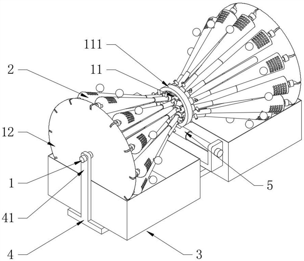
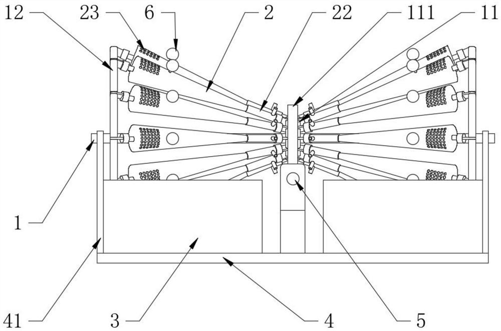
[0029] see Figure 1-3 , a jet-type anti-blocking and dust-reducing device used in mine development. This dust-reducing device is used to be placed at the front end of the belt conveyor used for mineral material transfer, that is, the position of the blanking end, and can be placed under the belt of the blanking material. It is a dust-affected area. The dust suppression device includes a horizontal bearing shaft 1, a water storage pipe 2, a water tank 3 and a bearing plate 4, wherein the bearing plate 4 plays a role in supporting the entire dust suppression device. The middle connecting round platform 11 and the end connecting disc 12 are distributed on the same axis. The number of the end connecting discs 12 is two and located on both sides of the middle connecting round platform 11. The two ends of the water storage pipe 2 are blind ends and one end is fixedly connected. There is a connecting shaft 21 fixedly connected to the outer wall of the end connecting disk 12, and the...
Embodiment 2
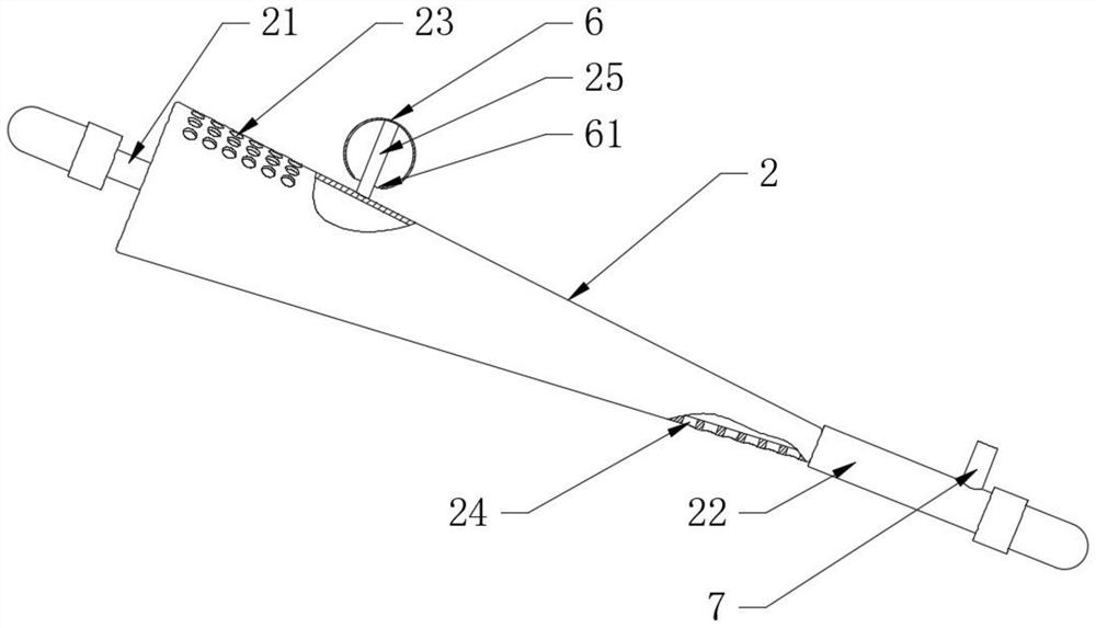
[0031] see image 3, and the difference from Embodiment 1 is that the outer wall of the water storage pipe 2 is fixedly connected with the watering can 6 close to the outer flow hole 23, the sprinkling mouth of the watering can 6 faces the outer wall of the water storage pipe 2, and the position of the watering can 6 is relatively The evenly distributed water storage pipes 2 are set outwards. Specifically, the outer wall of the water storage pipe 2 is fixedly provided with a connecting column 25. The watering pot 6 is spherical and has a water sprinkling hole 61 connected to the inner cavity on it. One end gap of the post 25 passes through the sprinkling hole 61 and is fixedly connected with the inner surface wall of the watering can 6, thus, when the large end of the water storage pipe 2 is submerged in the water, the watering can 6 is used for watering, when the water storage pipe 2 During the movement of the big end to the highest position, the water outlet of the watering ...
Embodiment 3
[0033] see Figure 4 , the difference with Embodiment 1 is that the outer wall of the air jet tube 22 is fixedly provided with an air jet tube 7 communicating with the inner cavity, and the orifice of the air jet tube 7 and the outer flow hole 23 is facing the same direction. The preferred air jet tube 22 includes an outer cylinder 221, Return spring 222 and piston disc 223, one end of the outer cylinder 221 is a blind end and the other end communicates with the water storage pipe 2, the piston disc 223 is slidably sleeved in the outer cylinder 221 and close to the water storage pipe 2, and the piston disc 223 passes through the return spring 222 and the outer cylinder 221 are elastically matched, and one end of the air jet pipe 7 is fixedly connected to the outer wall of the outer cylinder 221 and close to the middle connecting round table 11. In Embodiment 1, the water body in the water storage pipe 2 flows downward due to The principle of gravity will squeeze the piston dis...
PUM
 Abstract
Description
Claims
Application Information
 - R&D
- Intellectual Property
- Life Sciences
- Materials
- Tech Scout
- Unparalleled Data Quality
- Higher Quality Content
- 60% Fewer Hallucinations
Browse by: Latest US Patents, China's latest patents, Technical Efficacy Thesaurus, Application Domain, Technology Topic, Popular Technical Reports.
© 2025 PatSnap. All rights reserved.Legal|Privacy policy|Modern Slavery Act Transparency Statement|Sitemap|About US| Contact US: help@patsnap.com


