Check patentability & draft patents in minutes with Patsnap Eureka AI!

Actuating device

An actuating device and a technology of an actuating part, which are applied to components of a pumping device for elastic fluids, machines/engines, liquid fuel engines, etc. Effect

Pending Publication Date: 2021-05-11
KOGE MICRO TECH CO LTD
View PDF0 Cites 0 Cited by
  • Summary
  • Abstract
  • Description
  • Claims
  • Application Information

AI Technical Summary

Problems solved by technology

[0004] The present invention provides an actuating device, mainly an adjustment layer is provided between the bearing part, the piezoelectric unit, the conduction unit and the perforated sheet, and through the plane electrical connection inside the pump body, the overall appearance structure of the actuating device is highly flat It not only overcomes the problem of lower reliability in the welding manufacturing process in the past, but also achieves the purpose of flattening the appearance of the actuator and miniaturizing the volume by means of the internal planar electrical connection technology

Method used


Image

  • Actuating device
  • Actuating device
  • Actuating device

Examples


Embodiment Construction

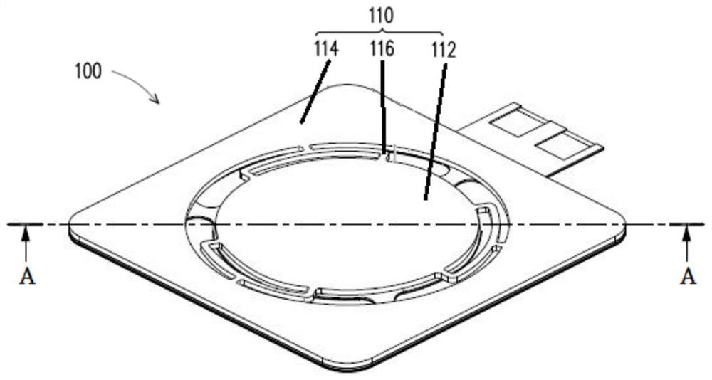
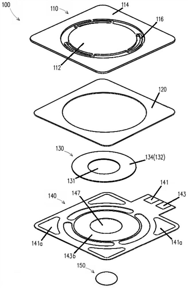
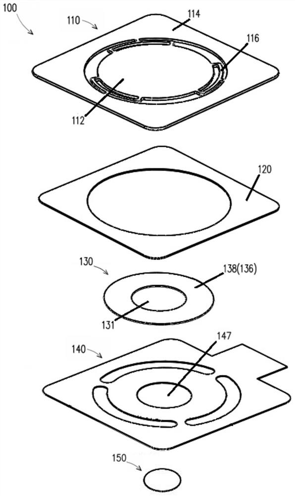
[0036] figure 1 is a schematic diagram of an actuating device according to the first embodiment of the present invention. figure 2 yes figure 1 An exploded schematic of the actuation device. image 3 yes figure 1 Another perspective exploded schematic view of the actuating device. Figure 4 yes figure 1 A-A line sectional schematic diagram of the actuating device. Figure 5 yes Figure 4 A partially enlarged schematic diagram of . see Figure 1 to Figure 5 , the actuation device 100 of this embodiment includes an actuation part 110 , a piezoelectric unit 130 , a bearing part 120 , an adjustment layer 160 , a conduction unit 140 and a perforated sheet 150 . The actuating device 100 will be described in detail below.

[0037] see figure 2 , in this embodiment, the actuation part 110 includes a first actuation area 112 , a second actuation area 114 and at least one connection section 116 between the first actuation area 112 and the second actuation area 114 . The fir...


PUM


Abstract

An actuating device comprises an actuating part, a piezoelectric unit, a bearing part, an adjusting layer, a conduction unit and a perforated sheet. The actuating part comprises a first actuating area, a second actuating area and at least one connecting section. The piezoelectric unit comprises a first through hole, a first signal area and a second signal area, and the two signal areas are electrically insulated from each other. The bearing part and the piezoelectric unit are located on the same plane. The adjusting layer is located on the same side surface of the piezoelectric unit and the bearing part. The conduction unit comprises a first conduction area, a second conduction area and a second through hole, the first signal area of the piezoelectric unit is electrically connected to the first conduction area of the conduction unit, and the second signal area of the piezoelectric unit is electrically connected to the second conduction area of the conduction unit. The perforated sheet is arranged at the corresponding positions of the first through hole and the second through hole, penetrates through the two through holes and then is fixed to the actuating part.

Description

technical field [0001] The present invention relates to an actuating device, in particular to an actuating device whose overall composition structure has uniform flatness through the design of the adjustment layer. Background technique [0002] The piezoelectric pump is a new type of fluid driver. It does not need an additional drive motor. It can deform the piezoelectric vibrator only through the inverse piezoelectric effect of the electroceramic, and then generate the volume change of the pump chamber according to the aforementioned deformation to achieve fluid output. Or the fluid can be transmitted through the vibration of the piezoelectric vibrator, so the piezoelectric pump has gradually replaced the traditional pump and is widely used in electronics, biomedicine, aerospace, automobile and petrochemical industries [0003] Generally speaking, a piezoelectric pump is composed of a piezoelectric unit and a pump body. When the piezoelectric unit is energized, the piezoele...

Claims


Application Information

Patent Timeline
IPC IPC(8): F04B43/04F04B53/00H02N2/00H02N2/04
CPCF04B43/046F04B43/0009H02N2/005H02N2/04
Inventor 吴宗翰王薪椉
Owner KOGE MICRO TECH CO LTD
Features
  • R&D
  • Intellectual Property
  • Life Sciences
  • Materials
  • Tech Scout
  • Unparalleled Data Quality
  • Higher Quality Content
  • 60% Fewer Hallucinations
Learn More