
Integrated electro-hydraulic servo rotary actuator

A rotary actuator and electro-hydraulic servo technology, applied in the field of servo actuators, can solve the problems of low control accuracy, small power density ratio and power volume ratio, and high space requirements.

Pending Publication Date: 2021-05-11
张岩
View PDF0 Cites 3 Cited by
  • Summary
  • Abstract
  • Description
  • Claims
  • Application Information

AI Technical Summary

Problems solved by technology

[0003] At present, hydraulic rotary mechanisms are being vigorously developed at home and abroad, and various forms of applications are being developed. Chinese patent application 201910318497.42 published "a hydraulic system and mechanical arm of a rotary electro-hydraulic actuator". The device uses a typical closed hydraulic circuit. Control the back and forth operation of the rack and pinion swing cylinder, but the device has the disadvantages of low control precision, low power density, and lack of integration and intelligence
[0004] At present, the valve industry mainly uses rack and pinion oscillating cylinders. Since its power density ratio and power volume ratio are much smaller than those of helical oscillating cylinders, it is limited in the shipping industry, petrochemical industry and other occasions that require high space.
In addition, regardless of the use of rack and pinion oscillating cylinders, or the use of helical oscillating cylinders, hydraulic energy is provided by hydraulic pump stations or hydraulic units, which will result in low power density ratio and power volume ratio
When a hydraulic pump station is used to supply oil, it will inevitably drag a long hydraulic pipeline and control line; when a hydraulic unit is used to supply oil, it will inevitably drag a long power circuit and control line, which undoubtedly increases the overall The complexity and unreliability of the control system

Method used


Image

  • Integrated electro-hydraulic servo rotary actuator
  • Integrated electro-hydraulic servo rotary actuator
  • Integrated electro-hydraulic servo rotary actuator

Examples


Embodiment Construction

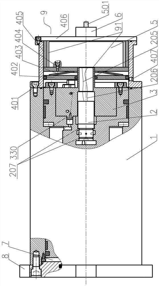
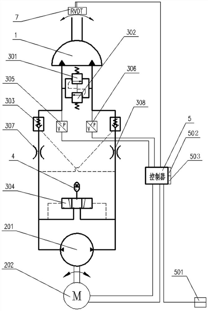
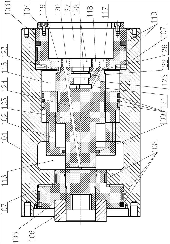
[0037] Integrated electrohydraulic servo rotary actuator, see Figure 1-Figure 8 : It includes a helical oscillating cylinder 1, an integrated motor pump 2, an integrated valve block 3, an accumulator 4, a controller 5, and an RVDT angle sensor 7. The helical oscillating cylinder 1 includes a cylinder body 101, an output shaft 103, and a piston 102. A piston 102 and an output shaft 103 are arranged in the inner chamber of the cylinder body 101. The piston 102 is meshed with the corresponding first meshing inner tooth of the inner chamber of the cylinder body 101 through the outer helical right tooth 113, and the outer cylindrical surface of the piston 102 is in contact with the cylinder body. The annulus of the inner wall of the inner cavity of the inner cavity is clearance fit to form a sealed contact connection. The connecting end of the output shaft 103 meshes with the inner helical left tooth 114 of the positioning cavity of the piston 102 through the outer helical left too...


PUM


Abstract

The invention provides an integrated electro-hydraulic servo rotary actuator which is characterized in that a hydraulic execution element, a hydraulic control element, a hydraulic power element, a sensor, a motor and a control system are modularly and integrally arranged, so that the power density ratio and the power volume ratio can be greatly improved, the system can be simplified, and system installation control, online real-time monitoring and intelligent protection are facilitated. The integrated electro-hydraulic servo rotary actuator comprises a spiral oscillating cylinder, an integrated motor pump, an integrated valve block, an energy accumulator, a controller and an RVDT angle sensor, the spiral oscillating cylinder comprises a cylinder body, an output shaft and a piston, the piston and the output shaft are arranged in an inner cavity of the cylinder body, the piston is connected with corresponding first meshing inner teeth of the inner cavity of the cylinder body in a meshing manner through outer spiral teeth, the outer cylindrical surface of the piston is in clearance fit with the annular surface of the inner wall of the inner cavity of the cylinder body, and the connecting end of the output shaft is meshed with inner spiral left teeth of a positioning cavity of the piston through outer spiral left teeth.

Description

technical field [0001] The invention relates to the technical field of servo actuators, in particular to an integrated electro-hydraulic servo rotary actuator. Background technique [0002] Because hydraulic drive has the advantages of high power density and smooth movement, hydraulic drive is used at some rotary joints with large loads or high control precision requirements. At present, hydraulic rotary actuators mainly include: helical swing cylinder, vane swing cylinder, rack and pinion swing cylinder, and the combination of linear cylinder and ball winch pair. [0003] At present, hydraulic rotary mechanisms are being vigorously developed at home and abroad, and various forms of applications are being developed. Chinese patent application 201910318497.42 published "a hydraulic system and mechanical arm of a rotary electro-hydraulic actuator". The device uses a typical closed hydraulic circuit. Control the back and forth operation of the rack and pinion swing cylinder, b...

Claims


Application Information

Patent Timeline
IPC IPC(8): F15B11/08F15B13/02F15B1/02F15B15/12F15B19/00F15B21/08
CPCF15B1/02F15B11/08F15B13/02F15B13/027F15B15/12F15B19/00F15B21/08
Inventor 张岩
Owner 张岩
Learn More