[0051]Example 1
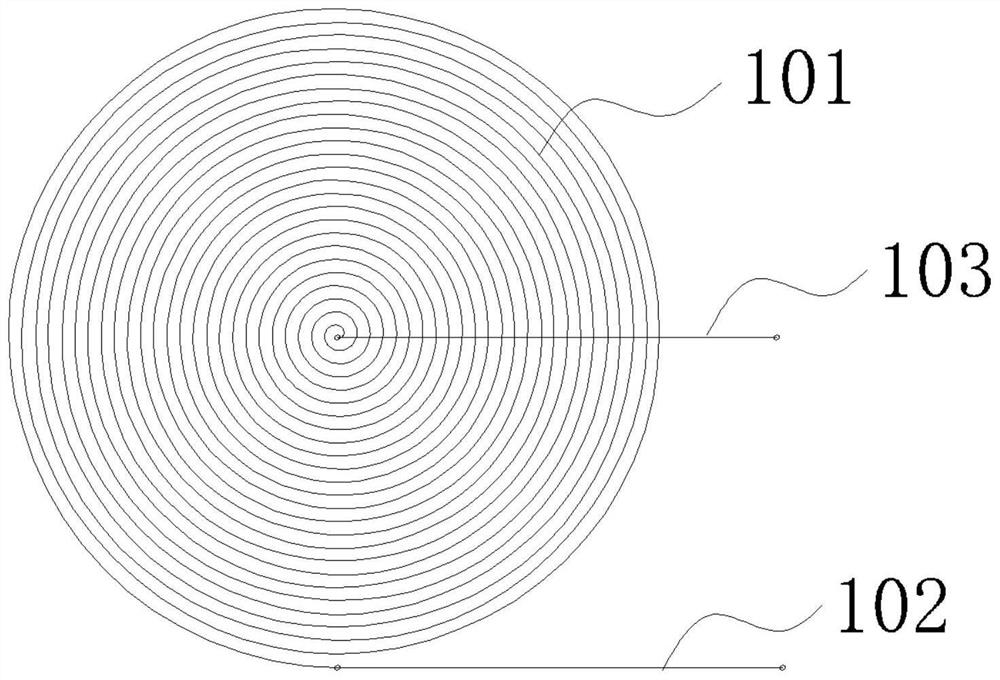
[0052]Such asfigure 1 As shown, the inductive spatial curvature measuring sensitive element includes: a circular conductive carbon ink coil 101, an interface lead 102, and an interface lead 103. The circularly conductive cartridge 101 is provided with a plurality of turns, and the adjacent turns is insulated. The interface lead 102 is connected to one end of the circular conductive carbon ink, and the interface leads 103 are connected to the other end of the circular conductive carbon ink coil 101. The material of the circle-type conductive carbon ink coil 101 is a conductive carbon ink.
[0053]When the sensitive component is measured by an inductive spatial curvature, the circular conductive carbon ink welding is printed or pasted on the measured object in a circular shape. When printing or paste, the number of turns as possible can increase the sensitivity of the sensitive element.
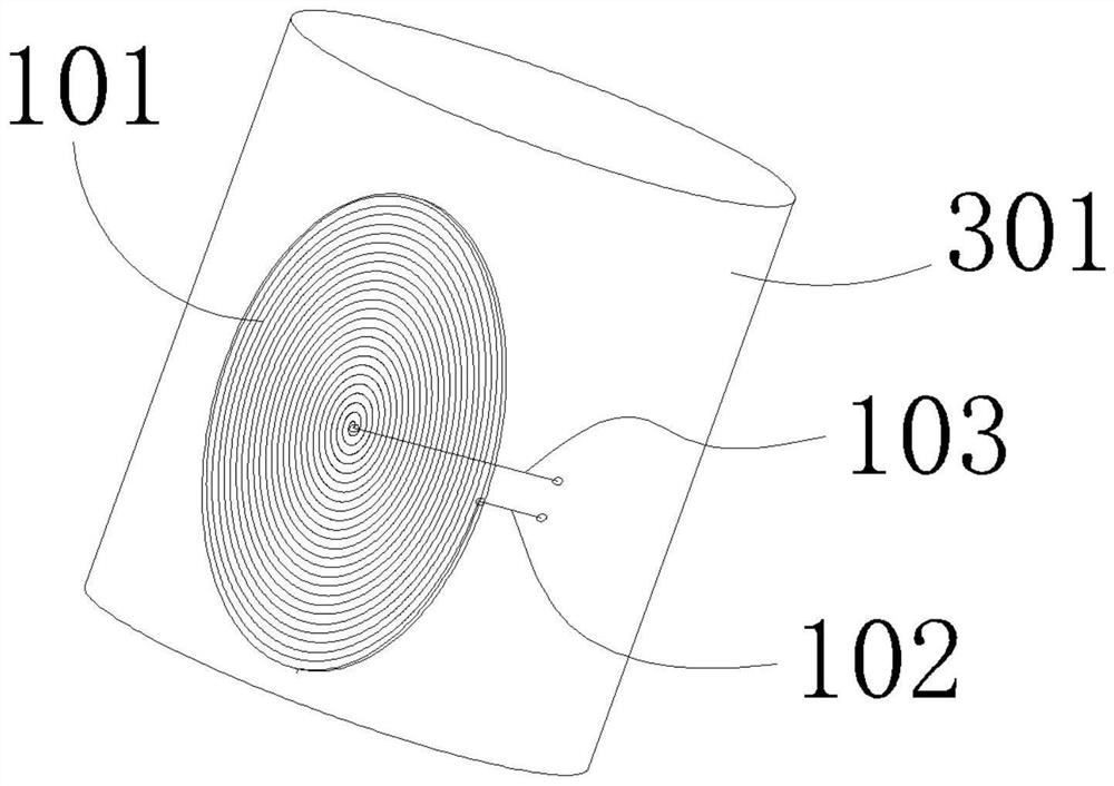
[0054]Such asfigure 2 As shown, the inductive spatial curvature measures the surface of the sensitive element screen printing at the surface of the subject 301. The circular conductive carbon ink coil 101 is insulated between the measured objects 301.
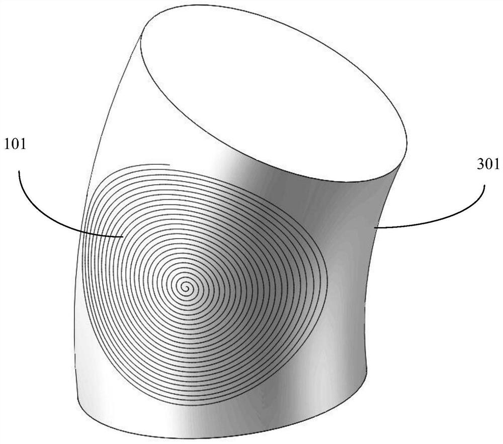
[0055]For the measured object 301, there is no limit on the length and width, and the circularly conductive carbon ink coil 101 of different sizes can be designed according to different needs. The measurement range of the inductive spatial curvature measurement sensitive element depends on the spatial magnetic field distribution of the circle type conductive carbon ink coil 101, rather than the distance between the turns of the circular conductive carbon ink, and therefore, the large curvature surface can be measured. Such asimage 3 As shown, when the bending deformation is generated by the measurement object 301, the circularly conductive carbon ink coil 101 is also deformed, and the spatial magnetic field structure of the circularly conductive carbon ink coil 101 changes, and the inductance value also generates an equal proportion or isometric change. The inductance value of the circular conductive carbon ink coil 101 is reduced due to deformation of its own spatial structure. When the calibration measurement is measured by the sensitive element of the present embodiment, the amount of deformation of the circular conductive carbon ink coil 101 can be obtained by measuring the inductance value of the circularly conductive carbon ink welding, and further know the object 301 The amount of deformation is obtained, thereby obtaining a variation value of an external parameter that causes the measured object 301 to change the curvature.
[0056]Such asFigure 4 with5As shown, the measuring circuit includes an operational amplifier OA, a resistance R, a positive phase input end of an operational amplifier OA, a reverse phase input end connected to the arithmetic amplifier OA, an inductive spatial curvature measuring the interface lead 103 and an operational amplifier of the sensitive element OA output is connected, and the inductive spatial curvature measures the interface lead 102 of the sensitive element to the inverting input end of the operational amplifier OA. Input voltage signal ViThe inverting input of the operation amplifier OA, output voltage signal VoAccess microcontroller for calculation.
[0057]Input voltage signal ViAnd output voltage signal VoThe formula is as follows:
[0058]Vi= Um S i nωt (1)
[0059]
[0060]Equation (1) and (2), ViIs the sinusoidal voltage signal, ω is the frequency of the signal generator; j is the unusual number of extracters, namely R is known resistance, resistance Rx, inductance LXFor the equivalent resistance, inductance of the measured electricity (ie, the inductive spatial curvature measurement sensitive element); the value of the resistor Rx is measured using LCR bridge instrument.
[0061]Above VoFormula (2) can be derived from LX:
[0062]
[0063]Inductive spatial curvature measures the inductance of sensitive components in a flat shape0, L0The value is measured with LCR bridge instrument. When the inductive space curvature measuring sensitive element is attached to the surface of the object 301, when the object 301 generates a bending deformation, the curvature θ of the object 301 can be derived by the following formula:
[0064]
[0065]Such asFigure 6 As shown, the relationship curve between the curvature of the measured object 301 and the inductive spatial curvature measurement sensitive element is calculated by MATLAB software.Figure 6 In the middle, the abscissa is the curvature θ, the ordinate is
[0066]The measured object 301 capable of bending the deformation can be a flexible robot arm (such as a flexible robotic arm of silica gel material).
[0067]The method of setting an inductive spatial curvature measurement sensitive component in the surface of the flexible robot arm is mainly included in the following steps:
[0068]Step S101, prepare a flexible robot arm;
[0069]In step S102, the wire screen printing 4 is made by the photographic material by the photographic version, so that the mesh 4-1 of the wire screen printing is a through hole, not the mesh hole of the coil portion being blocked, such asFigure 7 Indicated;
[0070]Step S103, the wire screen printing 4 is in close to the surface of the flexible robot arm, and a layer of carbon ink is applied to the wire screen 4, and the cartridge is extruded with a scraper 5, so that the carbon ink is printed on the screen. The mesh portion of the coil portion is transferred to the surface of the flexible robot arm, forming a circular conductive carbon ink coil 101 (egfigure 2 Indicated by it);
[0071]Step S104, the interface lead 102 is pasted through the adhesive to one end of the circularly conductive carbon engar coil 101, and the interface lead 103 is pasted to the other end of the circular conductive carbon ink coil 101 by a binder.
[0072]referenceFigure 8 with9Here, another method of setting an inductive spatial curvature measurement sensitive element in the surface of the flexible robot, mainly comprising the following steps:
[0073]Step S201, by using the photosensitive material through the photographic version of the method, the wire screen printing 4 is made, so that the mesh 4-1 of the wire screen printing the circular coil portion is a through hole, and the mesh hole of the non-coil portion is blocked, such asFigure 7 Indicated.
[0074]Step S202, prepare the first polyimide film 6, cut out the size of the required size according to the size of the flexible robot arm;
[0075]Step S203, the wire screen printing 4 is in close to the first polyimide film 6, and a layer of carbon ink is applied to the wire screen printing 4, and the carbon cartridge is extruded with a scraper. On the first polyimide film 6, a circularly conductive carbon ink coil 101 is formed, and an interface lead is attached to one end of the circular conductive carbon ink coil 101 with an adhesive to lead another interface lead. Paste the other end of the circular conductive carbon ink coil 101;
[0076]Step S204, the second polyimide film 7, the size, and the first polyimide film are prepared, and two lead holes (lead holes 7-1, 7-) are opened in the second polyimide film 7. 2);
[0077]Step S205, cover the second polyimide film 7 on the first polyimide film 6, one of the interface leads from the lead hole 7-1, and another interface lead from the lead hole 7 -2 is passed, and the second polyimide film and the first polyimide film are adhered to the first polyimide film (the outer edge of the second polyimide film and the first poly] The outer edge of the imine film is adhered together), the second polyimide film is an upper polyimide film, and the first polyimide film is a lower polyimide film.
[0078]Step S206, the lower polyimide film is pasted on the surface of the flexible robot arm with an adhesive.
[0079]The inductive spatial curvature measurement sensitive element made by this method can be reused, i.e., the lower polyimide film can be used directly from the surface of the flexible robot arm to be used in the next flexible robot arm.
[0080]In order to make the measurement result more accurate, the measurement system is calibrated, the calibration process is as follows: First, the data corresponding to the deformation and inductance of the side object is calculated, by measuring the size of the electrosphere value at the standard curvature; to prevent the calibration factor during the calibration process, Acquire data sets at multiple different curvatures. Second, the functional relationship of the inductance value-bending amount is followed by a neural network, and L = f (θ). Further, according to ifFigure 5 Circuit diagram, sweep through the 600 Hz sine wave emitted by the signal generator to obtain the resonant frequency when the inductance is resonant. Then, bring the resonant frequency value into the formula Calculate the inductance value. Finally, the function relationship L = f (θ) is recorded in a single chip, and the fitted curve is obtained.
[0081]It should be noted that the material of the circular conductive coil is not limited to the carbon ink, and may be a carbon-based conductive powder (such as graphite, carbon fiber), or a metal conductive powder (such as nano silver particles, metal fibers).
[0082]It should be noted that the polyimide film can be replaced by a flexible film such as a polyamide film. The mechanical properties, heat resistance, and electrical insulation performance of the polyimide film, the continuous use temperature of the polyimide film can be as high as 200 ° C, the volume resistivity is 1013Ω · cm. On the other hand, a polyimide film is used to facilitate a fixed connection between the flexible film and the object to be measured to prevent the flexible film to slide on the surface of the measured object.
[0083]The inductor coil varies with the change in the curvature of the object, relying on the elasticity of the flexible film to generate a greater elastic deformation capability of the inductor coil. The production process is simple, reliable production, reliable production, good production, and diversification of product production, and the advantage of manufacturing the low-cost circuit characteristics, which meets large quantities. Since it is a flexible film, the sensor has good flexibility, and at the same time having a sufficiently large bending deformation measurement range, there is a good structure flexibility, which can be applied to various objects having complex curved surfaces, such as software robots, have an industry. The use value of the engineering and engineering; also bending the deformation performance, it can be restored when the amount of bending is large, and it is not easy to occur in the case of the unrecoverable plastic stretching, and the repetition performance of multiple bending is good; The adjustment of the spacing between the coil width and the turns, which can maintain a good functional relationship with the curvature change value, and further improve the measurement accuracy and sensitivity of the measured parameters.