
Ultrasonic chromatography flow field imaging method and device

An imaging method, acoustic tomography technology, applied in the direction of measuring device, sound wave re-radiation, utilization of re-radiation, etc., can solve the problems of low spatial resolution, large sound propagation time measurement error, insufficient time resolution, etc., and achieve high precision and resolution improvement, overcome the effects of short detection distance and high spatial resolution

Active Publication Date: 2021-05-11
MINNAN NORMAL UNIV +1
View PDF10 Cites 2 Cited by
  • Summary
  • Abstract
  • Description
  • Claims
  • Application Information

AI Technical Summary

Problems solved by technology

These methods can only monitor the flow velocity in a small range, and cannot reflect the flow field distribution in a wide range of waters at the same time.
The existing application with the application number CN200810062069.1 discloses an acoustic flow measurement method and device, using low-frequency sound waves, the center frequency is 5kHz, and the bandwidth is 3-7kHz. Due to the low frequency, the measurement time of flow velocity in a small scale will inevitably be Insufficient resolution
The existing application with the application number CN201210073119.2 discloses an acoustic two-dimensional flow field measurement system and method, which is also only applicable to large-scale waters in the offshore ocean. Due to the large measurement error and low spatial resolution, it is difficult to obtain fine flow field distribution. It is necessary to develop high-precision imaging technology of high-frequency acoustic tomography in small-scale waters

Method used


Image

  • Ultrasonic chromatography flow field imaging method and device
  • Ultrasonic chromatography flow field imaging method and device
  • Ultrasonic chromatography flow field imaging method and device

Examples


Embodiment 2

[0084] Further provide an ultrasonic acoustic tomography flow field imaging method system for implementing the method described in Embodiment 1, characterized in that it includes:

[0085] The first ultrasonic extension unit and the second ultrasonic extension unit are used to send and receive ultrasonic signals at the boundary of the water area to be detected;

[0086] Acoustic propagation time difference set acquisition module, used to obtain the sound propagation time difference set of each pair of scanning points for mutual transmission and reception of sound;

[0087] The flow velocity relationship establishment module is used to obtain the distance between the line between each pair of scanning points, and the angle between the line between each pair of scanning points and the X axis, according to the connection line between each pair of scanning points and the described The flow velocity relationship of the flow field is established by the sound propagation time differe...


PUM


Abstract

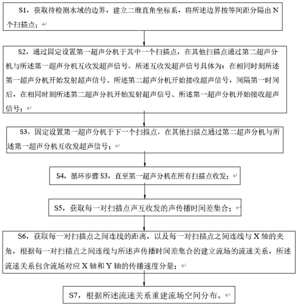
The invention relates to an ultrasonic chromatography flow field imaging method and device. The method comprises the following steps: S1, obtaining the boundary of a water area to be detected, building a two-dimensional rectangular coordinate system, and dividing the boundary into N scanning points at equal intervals; S2, fixedly arranging a first ultrasonic extension set at one scanning point, and mutually receiving and transmitting ultrasonic signals with the first ultrasonic extension set through a second ultrasonic extension set at other scanning points; S3, fixedly arranging the first ultrasonic extension set at the next scanning point, and transmitting and receiving ultrasonic signals with the first ultrasonic extension set through the second ultrasonic extension set at other scanning points; S4, circulating the step S3 till that the first ultrasonic extension set transmits and receives at all the scanning points; S5, acquiring an acoustic propagation time difference set of acoustic mutual transceiving of each pair of scanning points; S6, acquiring propagation velocity components of a flow field corresponding to an X axis and a Y axis in a flow velocity relation; and S7, reconstructing the spatial distribution of the flow field according to the flow velocity relation.

Description

technical field [0001] The invention relates to the field of flow field monitoring, in particular to an ultrasonic acoustic tomography flow field imaging method and a device thereof. Background technique [0002] The pollution of the estuary and near-coastal waters is becoming more and more serious. Tracing back to the source, most of the pollutants come from the land in the basin and are transported into the sea through the sea-land interface. The estuary-nearshore hydrodynamics are complex, and the flow field has significant spatial distribution characteristics. The research and development of online monitoring of the flow field in the estuary-nearshore sea area is extremely important for the major demand of offshore-watershed disaster prevention and mitigation. [0003] At present, the flow velocity in shallow sea and estuary waters is mainly measured by mechanical flowmeter, acoustic Doppler current profiler (ADCP) and other methods for fixed-point or mobile measurement....

Claims


Application Information

Patent Timeline
Patent Type & Authority Applications(China)
IPC IPC(8): G01S15/58G01S15/89
CPCG01S15/89G01S15/58Y02A90/30
Inventor 俞晓牮傅伟杰张宇
Owner MINNAN NORMAL UNIV
Learn More