Optimized structure of photovoltaic module

A technology for photovoltaic modules and structure optimization, applied in the field of solar modules, can solve the problems of reducing the service life of the cells, heating the cells, affecting the power generation of the modules, etc., to achieve the effect of reducing the impact

Pending Publication Date: 2021-05-11
CHANGZHOU ALMADEN
View PDF0 Cites 0 Cited by
  • Summary
  • Abstract
  • Description
  • Claims
  • Application Information

AI Technical Summary

Problems solved by technology

However, even if the battery string where the shaded cells are located is bypassed, the shaded cells are still heating, which greatly reduces the service life of the cells
According to the photovoltaic design standard, the spacing design of photovoltaic modules needs to meet the requirement that the shadow of the front row of modules will not block the rear row of modules between 9:00 am and 3:00 pm on the winter solstice, but there will still be shadows in the morning and evening, and if the site is small, the module spacing needs to be reduced , the front row will block the rear row more, and the rear row modules will produce hot spot effect due to the shading, and the power of the modules will drop, which will affect the power generation of the modules

Method used


Image

  • Optimized structure of photovoltaic module
  • Optimized structure of photovoltaic module
  • Optimized structure of photovoltaic module

Examples


Embodiment 1

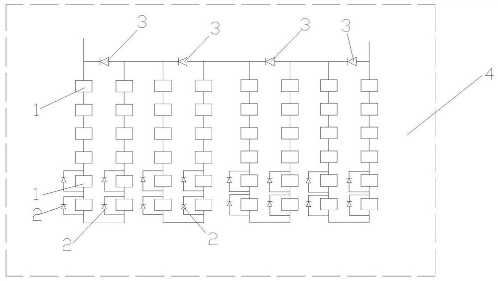
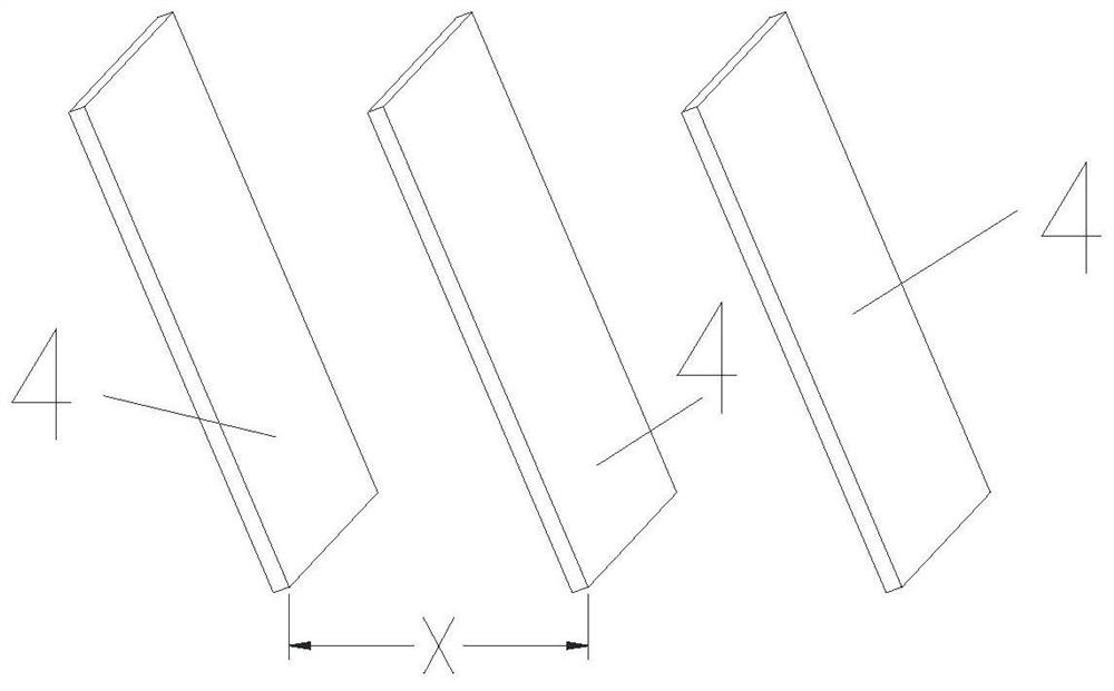
[0014] As shown in the figure, an optimized structure of a photovoltaic module includes several groups of photovoltaic modules 4, and each group of photovoltaic modules 4 is composed of cells 1 arranged in a matrix in series, between two adjacent groups of photovoltaic modules 4 The distance is X, and the photovoltaic modules 4 located in the rear of the two adjacent groups of photovoltaic modules 4 have a diode-2 connected between the positive and negative poles of the Y row of battery sheets 1, and the diode-2 is installed. The relationship between the row number Y of battery sheets 1 and the distance X between two adjacent groups of photovoltaic modules 4 is Y=round(-6.36X+11.09). Such as figure 1 As shown, this embodiment takes the vertical arrangement of battery slices 1 as an example for illustration. The number of battery slices 1 in the same row is 6, the number of battery slices 1 in the same row is 8, and there are two rows of battery slices 1 on the bottom. Diodes ...

Embodiment 2

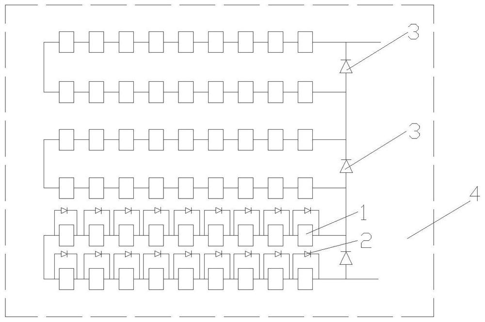
[0017] The difference from Embodiment 1 is that: figure 2 As shown, this embodiment is described by taking the horizontal arrangement of battery sheets 1 as an example. The number of battery sheets 1 in the same row is 6, and the number of battery sheets 1 in the same row is 9. There are two rows of battery sheets 1 on the bottom. Diode 1 is connected in parallel. The battery slices 1 arranged in matrix in each group of photovoltaic modules 4 are located between several battery slices 1 in the same row and connected in series to form a battery pack.

[0018] Effect verification: Both the conventional module and the optimized module are SEAC60-310W. The power generation of the two types of modules is compared through experiments. 20 groups of conventional and optimized modules are respectively connected to the same type of inverter and meter, installed facing south, and the inclination angle 23°, build a grid-connected system, and use a meter to record the power generation. ...


PUM


Abstract

The invention relates to an optimized structure of a photovoltaic module, and the structure comprises a plurality of groups of photovoltaic modules, wherein each group of photovoltaic modules is formed by serially connecting battery pieces arranged in a matrix, and the distance between the front and back adjacent groups of photovoltaic modules is X; a first diode is connected between the positive electrode and the negative electrode of Y rows of battery pieces at the bottom of the rear photovoltaic module in two adjacent groups of front and back photovoltaic modules, and the relation between the row number Y of the battery pieces provided with the first diodes and the distance X between the two adjacent groups of photovoltaic modules is Y = round (-6.36X + 11.09). According to the assembly design spacing, the optimal number of rows for installing the first diodes is selected, the spacing is reduced, the land utilization rate is improved, and the influence of shielding on the generating capacity of the assembly is reduced.

Description

technical field [0001] The invention relates to a solar component, in particular to an installation arrangement of a solar cell component. Background technique [0002] The development of new energy economy is the historical trend and inevitable choice of the world today. Photovoltaic power generation is an important type of new energy. Photovoltaic modules are the core components of photovoltaic power generation systems. During the operation of the components, there are light loss and electrical loss. Reducing these two types of losses will increase the power generation of the power station. Usually modules will produce hot spot effect due to shading. In order to prevent photovoltaic modules from being damaged due to hot spot effect, 20 (60 cells in series) or 24 (72 cells in series) cells in photovoltaic modules are connected in series. Then connect a bypass diode 1 in parallel. When the hot spot effect of the battery sheet fails to generate electricity, the diode will ac...

Claims


Application Information

Patent Timeline
Patent Type & Authority Applications(China)
IPC IPC(8): H01L31/05H01L31/044
CPCH01L31/0504H01L31/044Y02E10/50
Inventor 陈燕平林俊良林金锡林金汉
Owner CHANGZHOU ALMADEN
Why Eureka
Try Eureka