
Fuel cell hydrogen cycle test system

A test system and fuel cell technology, applied in fuel cells, fuel cell control, fuel cell additives, etc., can solve problems such as unsatisfactory overall power consumption and simple functions

Active Publication Date: 2021-05-11
SHANGHAI ELECTRICGROUP CORP
View PDF3 Cites 6 Cited by
  • Summary
  • Abstract
  • Description
  • Claims
  • Application Information

AI Technical Summary

Problems solved by technology

[0004] The technical problem to be solved by the present invention is to provide a fuel cell hydrogen cycle test system in order to overcome the defects of simple functions and unsatisfactory overall power consumption of the fuel cell hydrogen cycle test system in the prior art

Method used


Image

  • Fuel cell hydrogen cycle test system

Examples


Embodiment 1

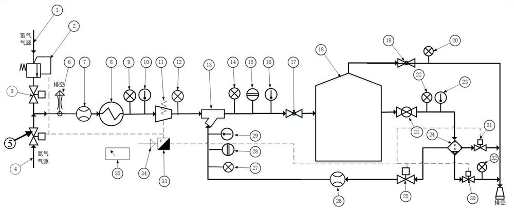
[0042] figure 1 A fuel cell hydrogen cycle test system of this embodiment is shown. It includes a hydrogen gas source 1, a dry hydrogen heat exchanger 8, a hydrogen circulation device 13, a heating and humidifying device 18, a first gas pipeline, a second gas pipeline, a third gas pipeline, an emptying pipeline, and a return pipe road. The hydrogen gas source 1 and the inlet of the dry hydrogen heat exchanger 8 are connected by a first gas pipeline, and the outlet of the dry hydrogen heat exchanger 8 is connected with the hydrogen inlet of the hydrogen circulation device 13 by a second gas pipeline. The hydrogen outlet of the circulation device 13 is connected to the inlet of the heating and humidifying device 18 through a third gas pipeline, the first outlet of the heating and humidifying device 18 is connected to the emptying pipeline, and the second outlet of the heating and humidifying device 18 is connected to the exhaust pipeline. The reflux inlets of the hydrogen circ...


PUM


Abstract

The invention discloses a fuel cell hydrogen cycle test system. A hydrogen gas source is connected with the inlet pipeline of a heat exchanger, the outlet of the heat exchanger is connected with the hydrogen inlet pipeline of a hydrogen cycle device, and the hydrogen outlet of the hydrogen cycle device is connected with the inlet pipeline of a heating and humidifying device; the first outlet of the heating and humidifying device is connected with an emptying pipeline, and the second outlet of the heating and humidifying device is connected with the reflux inlet of the hydrogen circulating device through a reflux pipeline; the heat exchanger adjusts the temperature of hydrogen supplied by the hydrogen source; the heating and humidifying device heats, humidifies and discharges the hydrogen; and the hydrogen circulating device sucks and reflows the hydrogen and supplies the hydrogen to the heating and humidifying device again. The heating and humidifying device is adopted to replace a galvanic pile, the actual consumption flow, pressure, temperature and humidity of the galvanic pile are completely simulated, heat exchange and humidifying are carried out on hydrogen, it is guaranteed that discharged hydrogen reaches a saturated state, and through suction backflow of the hydrogen circulating device, the characteristics of a fuel cell hydrogen circulating system are completely simulated and analyzed.

Description

technical field [0001] The invention belongs to the field of fuel cells, in particular to a fuel cell hydrogen cycle test system. Background technique [0002] With the update and practical application of fuel cell technology, in order to adapt to the new fuel cell technology and vehicle environment, the performance and structure of the fuel cell hydrogen circulation system will also change. In order to understand the change in its performance, it is necessary to develop a set of fuel cell The hydrogen cycle test system is used to analyze the performance of the hydrogen cycle system of the fuel cell in more detail and further improve the design of its structure. [0003] The existing fuel cell hydrogen circulation test system is basically connected. After the dry hydrogen is humidified through the heat exchange of a separate heater and humidifier, it is discharged through the buffer tank of the simulated stack cavity, and is discharged by the hydrogen circulation pump. It i...

Claims


Application Information

Patent Timeline
Patent Type & Authority Applications(China)
IPC IPC(8): H01M8/04298H01M8/0432H01M8/0438H01M8/04492H01M8/04089H01M8/04119
CPCH01M8/04305H01M8/04328H01M8/04343H01M8/04388H01M8/04402H01M8/045H01M8/04514H01M8/04097H01M8/04126Y02E60/50
Inventor 钱超林业发熊宇倪蕾蕾
Owner SHANGHAI ELECTRICGROUP CORP
Learn More