Inner stator assembly of hollow cup brush direct-current motor

A DC motor and inner stator technology, applied in the direction of magnetic circuit static parts, magnetic circuit shape/style/structure, etc., can solve the problem of affecting the working life and reliability of the motor, unfavorable bonding between the inner stator bracket and the permanent magnet, and the operation of the motor Sparks and electromagnetic interference and other problems, to achieve the effect of magnetization, saving permanent magnet materials, and improving magnetic performance

Inactive Publication Date: 2014-05-07
ONCE TOP MOTOR MFG
View PDF8 Cites 0 Cited by
  • Summary
  • Abstract
  • Description
  • Claims
  • Application Information

AI Technical Summary

Problems solved by technology

[0005] 1. When the circular permanent magnet is used, the magnetic flux density in the working air gap is relatively low, and the power density of the motor is relatively low;
[0006] 2. When the circular permanent magnet is used, the width of the commutation area is not easy to control, and the commutation conditions are relatively poor. There will be sparks and electromagnetic interference during the operation of the motor, which will directly affect the working life and reliability of the motor;
[0007] 3. The inner stator bracket adopts a cylindrical structure. Since the cylindrical surface of the inner stator bracket is smooth, it is not conducive to the bonding between the inner stator bracket and the permanent magnet. When the motor is running under load, there may be slipping between them and mechanical failure;

Method used


Image

  • Inner stator assembly of hollow cup brush direct-current motor
  • Inner stator assembly of hollow cup brush direct-current motor
  • Inner stator assembly of hollow cup brush direct-current motor

Examples


Embodiment Construction

[0038] The present invention will be further described in conjunction with the accompanying drawings and specific embodiments.

[0039] The present invention mainly solves the problems that the existing permanent magnets adopt ring-shaped permanent magnets, which are not easy to process, high processing cost, waste of materials, etc., and the problems of large commutation sparks, high noise and short service life of the motor.

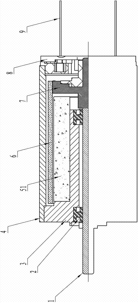
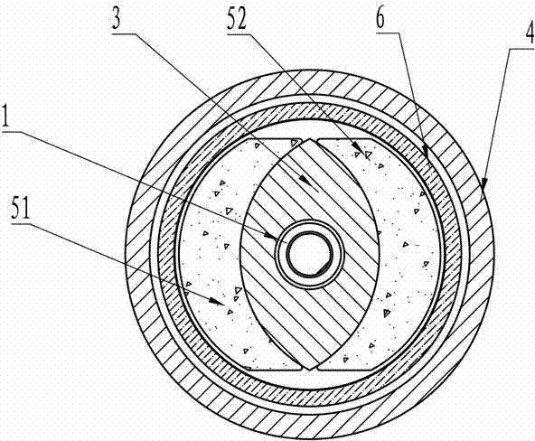
[0040] see figure 1 and figure 2 , a hollow cup brushed DC motor of the present invention, including a rotating shaft 1, bearings 2 (two), an inner stator bracket 3, a casing 4, a first permanent magnet 51 and a second permanent magnet 52, a wire cup 6, a Director 7, rear end cover 8 and brush 9 (two). The assembly relationship between them is described as follows: the rotating shaft 1, the commutator 7 and the wire cup 6 are combined into a rotor component, and the inner and outer diameters of the wire cup 6, the outer diameter of the commutator 7 ...


PUM


Abstract

The invention discloses an inner stator assembly of a hollow cup brush direct-current motor. The inner stator assembly is composed of an inner stator bracket and two permanent magnets symmetrically placed on the outer surface of the inner stator bracket. The two permanent magnets are tile-shaped permanent magnets with the same geometrical dimensions, and the radiuses of inner and outer arc surfaces of the permanent magnets are not in the same center of circle. During the assembly process of the motor, the two permanent magnets are simultaneously magnetized, one permanent magnet presents an N pole in a working air gap, and the other permanent magnet presents an S pole in the working air gap. The inner stator bracket is formed by mold pressing with the use of low-carbon steel, the two permanent magnets are symmetrically surface-mounted on the surface of the inner stator bracket, and the surface of the inner stator bracket is provided with a plurality of grooves so as to increase the bonding strength between the permanent magnets and the inner stator bracket. The performance of the motor can be obviously improved, and the operation service life and reliability of the motor can be increased; and meanwhile, the cost of products can be significantly reduced, and the market competitiveness of products can be improved.

Description

[0001] technical field [0002] The present invention relates to a hollow cup brushed direct current motor, more specifically, to an inner stator assembly of a hollow cup brushed direct current motor, the inner stator assembly includes an inner stator support and a permanent magnet. Background technique [0003] At present, in the structure of the hollow cup brushed DC motor, the inner stator assembly includes the inner stator bracket and the permanent magnet. Its permanent magnets are generally made into rings, and the outer surfaces of the inner stator brackets are all made into cylindrical shapes, and the ring-shaped permanent magnets are fixed on the inner stator brackets with an adhesive. For example, the utility model patent whose application number is 97223506.X discloses a rare-earth permanent magnet DC motor with double-ring magnetic pole parallel windings. Its inner stator bracket has a cylindrical outer circular surface, and its permanent magnet is in the shape of...

Claims


Application Information

Patent Timeline
Patent Type & Authority Applications(China)
IPC IPC(8): H02K1/17H02K1/18
Inventor 张用万
Owner ONCE TOP MOTOR MFG
Why Eureka
Try Eureka