Integrated antenna, manufacturing method thereof and integrated electronic device

An integrated antenna and manufacturing method technology, applied in the direction of antenna grounding switch structure connection, radiation element structure, etc., can solve the problems of short service life, low production efficiency, poor stability of integrated antenna connection, etc.

Pending Publication Date: 2021-05-11
ZINERGY SHENZHEN LTD
View PDF10 Cites 1 Cited by
  • Summary
  • Abstract
  • Description
  • Claims
  • Application Information

AI Technical Summary

Problems solved by technology

[0005] The purpose of the present invention is to provide an integrated antenna and its manufacturing method, and an integrated electronic device to solve the problem of poor stability of internal structure connection, short service life and low production efficiency of the integrated antenna in the prior art. Problems to be solved

Method used


Image

  • Integrated antenna, manufacturing method thereof and integrated electronic device
  • Integrated antenna, manufacturing method thereof and integrated electronic device
  • Integrated antenna, manufacturing method thereof and integrated electronic device

Examples


Embodiment approach

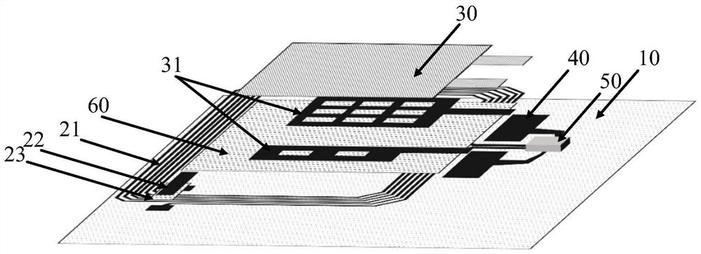
[0067] As a preferred embodiment, the thin film battery 30 includes a collector layer 31 . Some batteries have high internal resistance, so it is necessary to further print the collector layer 31 to reduce the internal resistance. The common collector layer 31 is a conductive paste layer, such as carbon paste and silver paste layer.

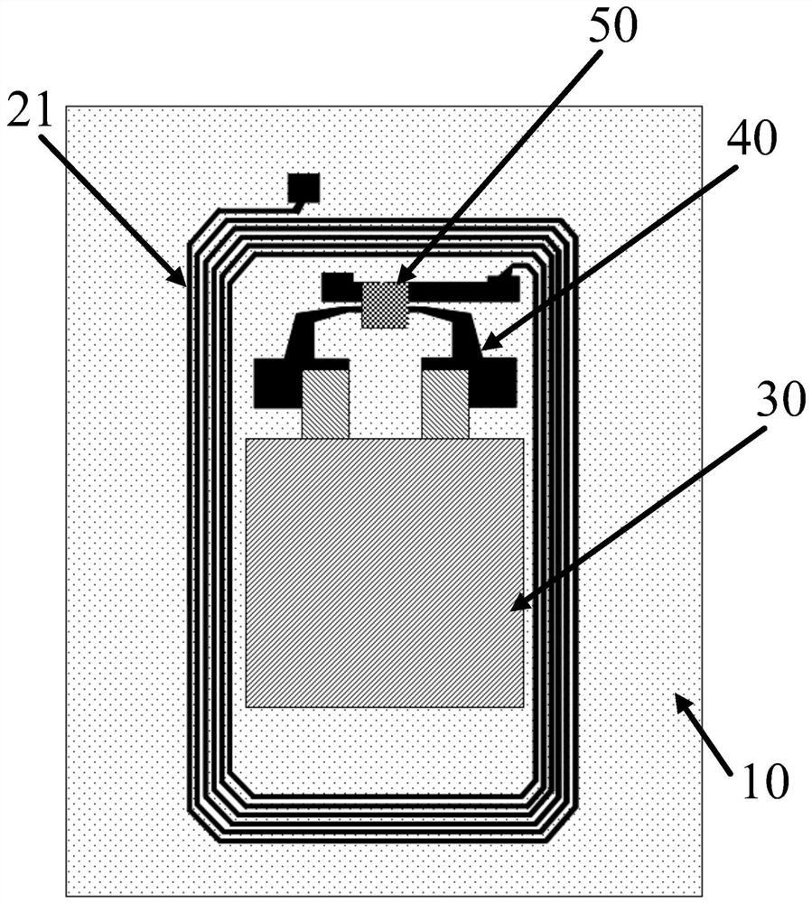
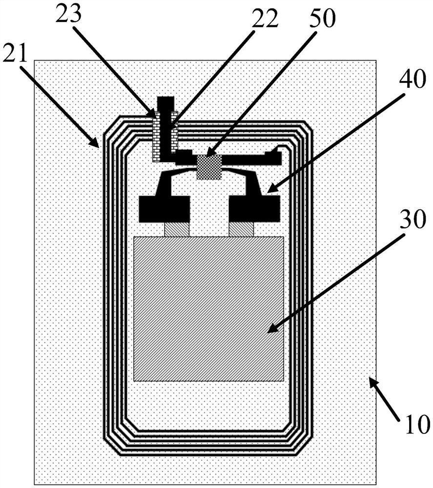
[0068] It should be noted that when the antenna conductive bridge 22 and the antenna coil 21 are arranged on the same side of the flexible substrate 10;

[0069] An antenna insulating bridge 23 is disposed between the antenna conductive bridge 22 and the antenna coil 21 .

[0070] Since the antenna coil 21 is generally ring-shaped, and the two ends are located on the inner side and the outer side of the ring respectively, to electrically connect these two ends, it must cross the ring itself, as Figure 5 Among them, on the other side of the flexible substrate 10 different from the antenna coil 21, it is connected through the antenna conductive b...

specific Embodiment approach 3

[0071] In addition, the present invention also provides a method for manufacturing an integrated antenna, the flow chart of which is shown in Figure 7 As shown, it is referred to as the third specific embodiment, including:

[0072] S1: setting the flexible substrate 10 .

[0073] S2: Printing and preparing thin film battery 30, radio frequency antenna 20 and power supply electrode 40 on the flexible substrate 10 to obtain an integrated front; wherein, the radio frequency antenna 20 includes an antenna coil 21 and an antenna conductive bridge 22; the antenna conductive bridge 22 connects the two ends of the antenna coil 21 and the thin film battery 30 is insulated from the radio frequency antenna 20; the thin film battery 30 is insulated from the radio frequency antenna 20.

[0074] The printing and preparation of thin film battery 30, radio frequency antenna 20 and power supply electrode 40 on the flexible substrate 10 includes:

[0075] printing the thin film battery 30 o...


PUM


Abstract

The invention discloses an integrated antenna which comprises a flexible substrate, a radio frequency antenna, a thin film battery and a power supply electrode. The radio frequency antenna comprises an antenna coil and an antenna conductive bridge; the antenna conductive bridge is connected with the two ends of the antenna coil, so that the antenna coil forms a closed loop with only one group of positive and negative ports; the thin film battery is in printing connection with the power supply electrode, and a tab of the thin film battery is electrically connected with the power supply electrode; and the thin film battery is printed on the flexible substrate and is insulated from the radio frequency antenna. According to the invention, the tabs of the thin film battery are directly printed on the power supply electrodes, so that the connection stability is greatly improved, good electric connection is realized, and the working stability of the integrated antenna is improved; in addition, different parts are prevented from being produced separately in the production of the integrated antenna, and the production efficiency of the integrated antenna is improved. The invention further provides a manufacturing method of the integrated antenna with the advantages and an integrated electronic device.

Description

technical field [0001] The invention relates to the field of integrated electronics, in particular to an integrated antenna, a manufacturing method thereof, and an integrated electronic device. Background technique [0002] With the rise of the Internet of Things, radio frequency identification technology has been widely used as its basic technology. Therefore, how to manufacture low-cost RFID tags with high yield becomes very important. Compared with passive RFID tags, active or semi-active RFID tags have longer read and write distances and more sensitive responses due to external power activation or additional detection functions. When the corresponding sensors (such as thermal and mechanical sensors) are integrated in the active or semi-active tag, the tag can further realize the function of recording and monitoring the corresponding sensing parameters, and the important structure is the integration of the antenna part and the power supply part. [0003] However, the an...

Claims


Application Information

Patent Timeline
Patent Type & Authority Applications(China)
IPC IPC(8): H01Q1/38H01Q1/50
CPCH01Q1/38H01Q1/50
Inventor 聂赞相罗师强普里帖斯·希亚拉迪乐克·奥兹特赵少彬
Owner ZINERGY SHENZHEN LTD
Why Eureka
Try Eureka